background image

R

epair

P 8 / 10 

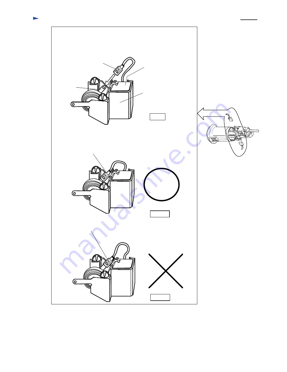
< 6 > Attaching carbon brush
          Connect the receptacle of carbon brush with the terminal of brush holder 
          by pushing in the direction of the arrow, as illustrated in Fig. 5.

Terminal of 
brush holder

Receptacle of carbon brush

Carbon brush

Brush holder

Push the receptacle of carbon brush until it stops as illustrated in Fig. 4A.

Incompletely attached receptacle 
of carbon brush

Completely attached receptacle 
of carbon brush

Fig. 5

Fig. 5A

Fig. 5B

Содержание 9566C

Страница 1: ...ontrol Super Joint System SJS The features of 9566CV Pre setting dial for speed control is added to the 9566C s features Dimensions mm Width W Height H Length L 299 11 3 4 169 6 5 8 103 4 1 16 W L H M...

Страница 2: ...r coming from accidental wheel lock All ball bearings are firmly protected from dust Comparison of products for USA Brazil and Switzerland Wheel size Specifications Model No Assorted wheel Diameter mm...

Страница 3: ...4 1 16 299 11 3 4 139 5 1 2 103 4 1 16 22 23 7 8 22 23 7 8 22 23 7 8 22 23 7 8 22 23 7 8 22 23 7 8 1 8 4 0 1 8 4 0 2 0 4 4 299 11 3 4 166 6 1 2 106 4 3 16 323 12 3 4 168 6 5 8 110 4 5 16 1 9 4 2 300 1...

Страница 4: ...ousing And remove armature with gear housing cover as illustrated in Fig 1 3 Disassemble retaining ring S 6 and flat washer 6 from armature shaft as illustrated in Fig 1A 5 Disassemble spiral bevel ge...

Страница 5: ...r 12 to armature shaft as illustrated In Fig 2A No 1R045 Gear extractor large Fig 1D Fig 1E 3 Assembling spiral bevel gear 9 and armature 1R217 Ring 22 Flat washer 21 Lock spring 12 Retaining ring S 1...

Страница 6: ...ning anti clockwise as illustrate in Fig 3B 4 Disassemble ball bearing 6201DDW by slightly hitting the edge of bearing box with plastic hammer as illustrate in Fig 3D Hex socket head bolt M4 x 16 with...

Страница 7: ...ated in Fig 4B 5 Assemble the gear section to gear housing by fastening with 4 pcs of hex socket head bolts M4 x 16 as illustrated in Fig 4C Fig 4B Fig 4C 1R028 Bearing setting pipe Spiral bevel gear...

Страница 8: ...in the direction of the arrow as illustrated in Fig 5 Terminal of brush holder Receptacle of carbon brush Carbon brush Brush holder Push the receptacle of carbon brush until it stops as illustrated in...

Страница 9: ...ue Switch block side Controller side Put the lead wires of controller in the lead holder so that they are not slacken Be careful not to loosen the lead wires of field in motor housing Put the loosened...

Страница 10: ...the place as illustrated in Fig 8 Do not loosen the lead wires of filed in motor housing Put the loosened ones in the place as illustrated in Fig 8 Put lead wires of power supply cord by strain relief...

Отзывы: