
P 7 / 8
R
epair
[3] -4. Hammer Mechanism and Spindle Section (cont.)
DISASSEMBLING
Fig. 19
Fig. 20
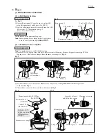
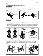
5) Now Hammer mechanism can be disassembled as illustrated in Fig. 19.
6) After removal of Flat washer 24, twenty-four 3.5 Steel balls can be removed from Hammer. (Fig. 20)
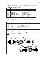
Spur gear 22
Flat washer 12
Pin 5
Hammer
Hammer
Compression
spring 25
Cup
washer 14
Steel ball 3.5
(24 pcs.)
Spindle
Flat washer 24
Spindle section
ASSEMBLING
Fig. 21
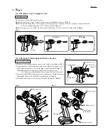
Hammer
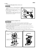
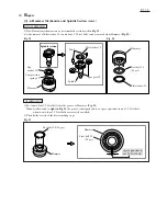
1) Put twenty-four 3.5 Steel balls into the groove of Hammer. (Fig. 21)
Note: As illustrated to right in Fig. 21, the groove is designed to have a space equivalent to one 3.5 Steel ball
when twenty-four 3.5 Steel balls are correctly installed.
2) Then do the reverse of the disassembling steps.
Hammer
Steel ball 3.5
(24 pcs)
space equivalent to
one 3.5 Steel ball
Steel ball 3.5 (24 pcs)


