


7 - 28
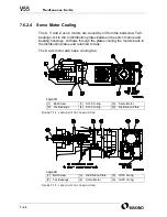
7.6.4
Ball Screw Pre-Tension
The X, Y, and Z ball screws are pre-tensioned (stretched) at installation to
minimize changes in axis positioning due to thermal growth of the screw.
When an axis moves, heat is generated by the recirculating balls in the
nut. The screw is subject to thermal growth by the coefficient of thermal
expansion (12 x 10-6/C°).
The screw shaft grows 0.012/1000mm (0.00047/39.37") with a tempera-
ture rise of 1° C (1.8° F).
The average ball screw temper-
ature rise is 3 to 4° C (5.4 to 7.2°
F). Pre-tensioning places a cold
screw under tension. The ten-
sion decreases or normalizes,
as the ball screw expands
toward its normal operating tem-
perature, minimizing axis posi-
tion deviation.
lists the pre-tension amounts for each axis.
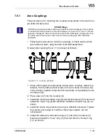
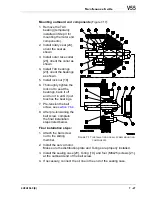
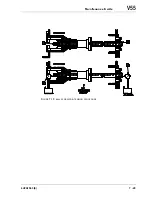
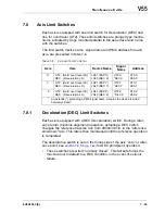
7.6.4.1
Pre-Tension Procedure
If the ball screw has been released or removed for any reason, follow this
procedure to pre-tension the ball screw.
Before mounting the X, Y, or Z axis servo motor:
1. Mount the ball screw [1], see
.
2. Tighten the outboard end lock nut [2], to seat the bearings.
3. Loosen lock nut [2] and run it back in to touch the bearings.
4. Place an indicator [3] and [4] on each end of the ball screw and set the
indicator to zero. (Be sure to load the indicator at about mid-range.)
5. Tighten lock nut [2] until the difference in the reading on indicator B
and indicator A equals the pre-tension amount for the axis,
6. Mount the servo motor, see
7. Check the axis reference points and reset, if necessary.
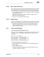
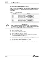
T
ABLE
7-6
BALL
SCREW
PRETENSION
AMOUNTS
Axis
X = B-A
(MM)
X = B-A
(INCH)
X
0.054
0.0021
Y
0.035
0.0014
Z
0.035
0.0014
Содержание V55
Страница 6: ...vi...
Страница 32: ...1 24 NOTES SKETCHES...
Страница 37: ...4V2A1563 E 2 3 FIGURE 2 1 SPINDLE POWER AND TORQUE CHARACTERISTICS...
Страница 39: ...4V2A1563 E 2 5 FIGURE 2 2 AXIS CONFIGURATION TRAVEL AND WORK CUBE...
Страница 41: ...4V2A1563 E 2 7 FIGURE 2 4 WORKPIECE SIZE LIMITATIONS...
Страница 53: ...4V2A1563 E 2 19 FIGURE 2 6 FLOOR SPACE FOR STANDARD MACHINE...
Страница 58: ...2 24 F IGURE 2 7 V55 WITH 25 TOOL ATC...
Страница 59: ...4V2A1563 E 2 25 F IGURE 2 8 V55 WITH 25 TOOL ATC AND LIFT UP CHIP CONVEYOR LEFT...
Страница 60: ...2 26 F IGURE 2 9 V55 WITH 25 TOOL ATC AND LIFT UP CHIP CONVEYOR RIGHT...
Страница 61: ...4V2A1563 E 2 27 F IGURE 2 10 V55 WITH 25 TOOL ATC LIFT UP CHIP CONVEYOR LEFT AND APC...
Страница 62: ...2 28 F IGURE 2 11 V55 WITH 25 TOOL ATC LIFT UP CHIP CONVEYOR RIGHT AND APC...
Страница 63: ...4V2A1563 E 2 29 F IGURE 2 12 V55 WITH 40 OR 80 TOOL ATC...
Страница 64: ...2 30 F IGURE 2 13 V55 WITH 40 OR 80 TOOL ATC AND LIFT UP CHIP CONVEYOR LEFT...
Страница 65: ...4V2A1563 E 2 31 F IGURE 2 14 V55 WITH 40 OR 80 TOOL ATC AND LIFT UP CHIP CONVEYOR RIGHT...
Страница 66: ...2 32 F IGURE 2 15 V55 WITH 40 OR 80 TOOL ATC LIFT UP CHIP CONVEYOR LEFT AND APC...
Страница 67: ...4V2A1563 E 2 33 F IGURE 2 16 V55 WITH 40 OR 80 TOOL ATC LIFT UP CHIP CONVEYOR RIGHT AND APC...
Страница 68: ...2 34 NOTES SKETCHES...
Страница 93: ...4V2A1563 E 3 23 FIGURE 3 6 LEVELING BASE POSITIONS AND BED TO FLOOR CLEARANCE...
Страница 94: ...3 24 NOTES SKETCHES...
Страница 99: ...4V2A1563 E 4 3 FIGURE 4 1 MACHINE CORE ELEMENTS...
Страница 103: ...4V2A1563 E 4 7 FIGURE 4 3 MAKINO PROFESSIONAL 3 CONTROL WITH MPC5...
Страница 106: ...4 10 NOTES SKETCHES...
Страница 114: ...4 18 NOTES SKETCHES...
Страница 123: ...4V2A1563 E 5 5 FIGURE 5 1 BASIC TROUBLESHOOTING FLOW CHART...
Страница 124: ...5 6 NOTES SKETCHES...
Страница 143: ...4V2A1563 E 5 25 NOTES SKETCHES...
Страница 153: ...4V2A1563 E 5 35 NOTES SKETCHES...
Страница 159: ...4V2A1563 E 5 41 NOTES SKETCHES...
Страница 166: ...5 48 NOTES SKETCHES...
Страница 191: ...4V2A1563 E 5 73 TEC F IGURE 5 26 S CHEMATIC PAGE FORMAT...
Страница 197: ...4V2A1563 E 5 79 NOTES SKETCHES...
Страница 198: ...5 80 NOTES SKETCHES...
Страница 202: ...NOTES SKETCHES...
Страница 227: ...4V2A1563 E 6 25 NOTES SKETCHES...
Страница 252: ...6 50 NOTES SKETCHES...
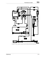
Страница 261: ...4V2A1563 E 6 59 FIGURE 6 36 SPINDLE HYDRAULIC CIRCUIT...
Страница 267: ...4V2A1563 E 6 65 FIGURE 6 40 L PORT SPINDLE LUBRICATION...
Страница 269: ...4V2A1563 E 6 67 FIGURE 6 41 V PORT SPINDLE LUBRICATION...
Страница 277: ...4V2A1563 E 6 75 NOTES SKETCHES...
Страница 279: ...4V2A1563 E 6 77 FIGURE 6 48 SEALING ROD INSTALLATION...
Страница 284: ...6 82 NOTES SKETCHES...
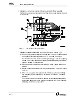
Страница 293: ...4V2A1563 E 7 5 F IGURE 7 3 AXIS DRIVE CIRCUIT...
Страница 297: ...4V2A1563 E 7 9 NOTES SKETCHES...
Страница 309: ...4V2A1563 E 7 21 FIGURE 7 12 BALL SCREW COOLING OIL AND TAC BEARING LUBRICATION PIPING...
Страница 311: ...4V2A1563 E 7 23 NOTES SKETCHES...
Страница 317: ...4V2A1563 E 7 29 FIGURE 7 18 BALL SCREW PRE TENSION PROCEDURE...
Страница 331: ...4V2A1563 E 7 43 FIGURE 7 26 Y AXIS LIMIT SWITCH TO DOG SETTINGS FIGURE 7 27 Z AXIS LIMIT SWITCH TO DOG SETTINGS...
Страница 346: ...7 58 NOTES SKETCHES...
Страница 348: ...7 60 FIGURE 7 35 Y AXIS COVER SYSTEM...
Страница 351: ...4V2A1563 E 7 63 NOTES SKETCHES...
Страница 369: ...4V2A1563 E 7 81 NOTES SKETCHES...
Страница 370: ...7 82 NOTES SKETCHES...
Страница 374: ...NOTES SKETCHES...
Страница 386: ...8 12 NOTES SKETCHES...
Страница 403: ...4V2A1563 E 8 29 NOTES SKETCHES...
Страница 423: ...4V2A1563 E 8 49 NOTES SKETCHES...
Страница 432: ...8 58 NOTES SKETCHES...
Страница 439: ...4V2A1563 E 9 5 NOTES SKETCHES...
Страница 441: ...4V2A1563 E 9 7 F IGURE 9 3 OIL CONTROLLER ELECTRICAL DRAWINGS...
Страница 443: ...4V2A1563 E 9 9 FIGURE 9 4 OIL CONTROLLER MACHINE SYSTEM...
Страница 464: ...9 30 NOTES SKETCHES...
Страница 468: ...NOTES SKETCHES...
Страница 490: ...A 22 NOTES SKETCHES...
Страница 525: ...4V2A1563 E A 57 NOTES SKETCHES...
Страница 526: ...A 58 NOTES SKETCHES...
Страница 534: ...B 6 NOTES SKETCHES...
Страница 546: ...B 18 NOTES SKETCHES...
Страница 558: ...B 30 NOTES SKETCHES...
Страница 564: ...B 36 NOTES SKETCHES...
Страница 568: ...B 40 NOTES SKETCHES...


