4.
(A)
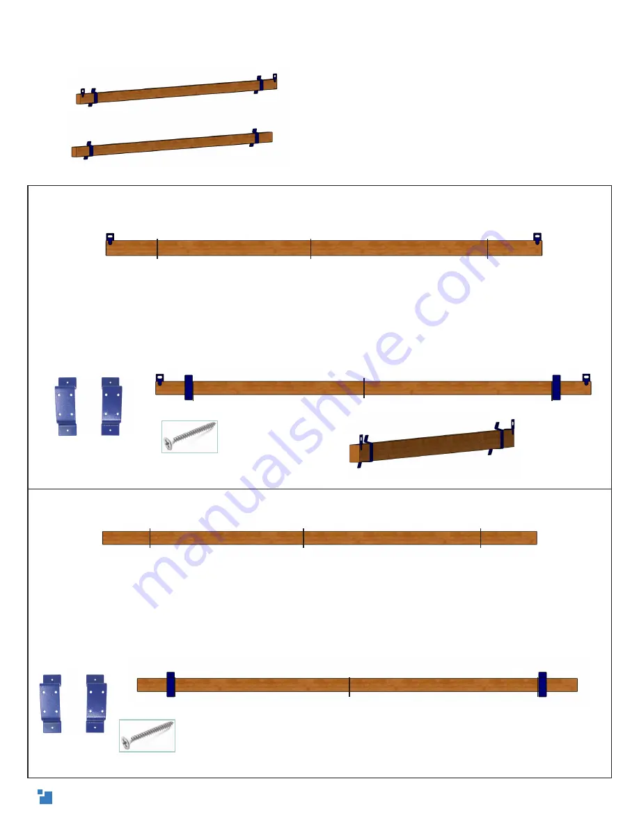
On the front face of the top beam, measure and mark 51.5in (130.8cm) from the center on
each side. Draw a straight line with the speed square.
(B)
Position a
stud mount
on the outside of each 51.5in line, with the shorter angle of the stud
mounts toward the top. On one side, push the bottom of the mount against the bottom of the top
beam, use a speed square as a guide to keep it on the 51.5in line, and screw it into the top beam
with four
short wood screws
. The bottom of the mount should be as flush as possible with the
bottom of the top beam and exactly perpendicular to the beam. Repeat on the other side. Use
the above Drew’s Note for mounting tips!
5.
(A)
On the front 4in face of the bottom beam, measure and mark 51.5in (130.8cm) from the
center on each side. Draw a straight line with the speed square.
(B)
Exactly like attaching to the top beam, position a
stud mount
on the outside of each 51.5in
line, with the shorter angle of the stud mounts toward the top. On one side, push the bottom of
the mount against the bottom of the top beam, use a speed square as a guide to keep it on the
51.5in line, and screw it into the top beam with four
short wood screws
. The bottom of the mount
should be as flush as possible with the bottom of the top beam and exactly perpendicular to the
beam. Repeat on the other side.
Attaching the stud mounts
Drew’s Note: For the M2’s alignment calibration
calculation (that’s fun to say), we have to
make sure that the stud mounts are exactly
perpendicular to the beams. To ensure this,
attach each screw part-way before moving
to the next. Repeat on the other two holes and
screw in each from opposite sides by small
increments until they are all tight - just like
changing a tire.
1.5in short wood screw
center
51.5in
51.5in
center
51.5in
51.5in
center
51.5in
51.5in
center
51.5in
51.5in
1.5in short wood screw
stud mount
Side view
stud mount
7


