


56, chemin de la Flambère · 31300 Toulouse · FRANCE · T é l . 3 3 ( 0 ) 5 6 1 3 1 8 6 8 7
F a x 3 3 ( 0 ) 5 6 1 3 1 8 7 7 3 · [email protected] · www.majorcom.fr
56, chemin de la Flambère · 31300 Toulouse · FRANCE · T é l . 3 3 ( 0 ) 5 6 1 3 1 8 6 8 7
F a x 3 3 ( 0 ) 5 6 1 3 1 8 7 7 3 · [email protected] · www.majorcom.fr
6
7
EMAGP16
EMAGP16
EW-SCREEN
MAJORCOM TOUCH SCREEN DIGITAL CONTROL
Usermanual V1.1
Usermanual V1.1
5.
INSTALLATION AND CONNECTIONS
5.1. Installation
EW-SCREEN is suitable for surface and desktop mount:
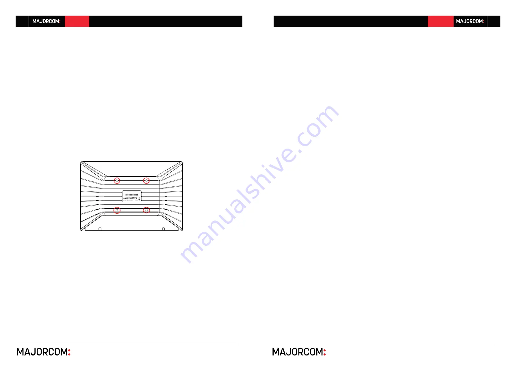
•
Surface mount: a VESA75 wall mount bracket is included with the product. It is composed
of two parts: the metal plate that must be assembled to the back panel of the EW-
SCREEN unit, with the 4 included screws, and the metal plate that must be assembled to
the wall or surface. Once both plates have been assembled and secured, the unit can be
fixed fitting them together and screwing the included security screw, with the included
tool for it
Note:
the VESA75 standard allows mounting the EW-SCREEN unit using other
third-party VESA75 brackets or stands
•
Desktop mount: the unit includes a stick shaped support that can be screwed to a thread
at the back panel of the EW-SCREEN unit, once the back panel connections cover is re
-
moved (fixed by 2 screws). Once installed, this stick allows to hold the EW-SCREEN unit
on a desktop surface, in a position closed to the vertical.
5.2. Connections
EW-SCREEN has 2 connectors available for the MajorcomNetoperation. Both are located behind
the rear panel connections plastic cover, fixed to the EW-SCREEN unit back panel with 2 screws:
•
DC Power: round jack for connection to the universal power supply provided with the
product, 12 VDC, 2A
•
Ethernet Port: RJ45 connector of the unit’s network communication interface, as well as
PoE DC supply compatible, in case the network switch is able to provide PoE (Power over
Ethernet) to it. It can be directly connected (point-to-point) to a single MajorcomNetde
-
vice, for its direct and exclusive control, or to an-Ethernet switch port belonging to the
network the rest of the MajorcomNetdevices of the installation are connected to. The
connecting cable can be a standard or crossover CAT5 or higher cable.
6.
OPERATION
From MajorcomNetManager application, it’s possible to create remote control panels for the system
(UCPs) to manage one or more PXN88, etc. units in a networked installation. Each panel can consist
of one or more pages that include graphics, text, volume controls, buttons, VU meters, LED indicators,
and so on. In this way, each remote user may have his own control panel(s) custom tailored to his needs
and privileges, and in one system, very simple control panels for some users can coexist with others,
more complex and having higher levels of authorization.
Once the UCPs are created, included in an MajorcomNet project, the network needs a web server
for the potential web clients that will control the installation thanks to the UCPs they can recall from
the web server, locally visualized and managed. The web server can be one of these types of devices:
•
A EW-SCREEN unit running the MajorcomNet project previously created with the Ma
-
jorcomNetManager application
•
A WPmSCREEN unit running the MajorcomNetproject previously created with the Ma
-
jorcomNetManager application
•
A MIMO4040DN matrix running the MajorcomNetproject previously created with the
MajorcomNetManager application
•
A Windows® PC running the created Majorcom NetManager project in “Deploy”
mode


