background image

50

53D0419

Designer Series Gas Fireplaces

NoTE REGaRDING VENTED PRoDuCTS

This product must be installed by a licensed plumber or gas fitter 
when installed within the Commonwealth of Massachusetts.
Any  residence  with  a  direct  vent  product  must  have  a  CO 
detector installed in the residence.
Installation  of  the  fireplace  or  vented  gas  log  in  the  State  of 
Massachusetts requires the damper to be permanently removed 
or welded in the fully open position.
In addition, a naturally vented gas log may not be installed in a 
bedroom or bathroom in the State of Massachusetts.
Flex line installation must not exceed 36 inches and must have 
a T shutoff valve. 

NoTE REGaRDING VENT FREE PRoDuCTS

This product must be installed by a licensed plumber or gas fitter 
when installed within the Commonwealth of Massachusetts.
In  addition,  vent  free  products  may  not  be  installed  in  a 
bedroom or bathroom regardless of size or type in the State of 
Massachusetts.
Flex line installation must not exceed 36 inches and must have 
a T shutoff valve.

CaRBoN MoNoxIDE DETECToR REquIREMENTS

(2) Revise  10.8.3  by  adding  the  following  additional 
requirements:
(a)  

For  all  side  wall  horizontally  vented  gas  fueled 

equipment installed in every dwelling, building or structure used 
in  whole  or  in  part  for  residential  purposes,  including  those 
owned or operated by the Commonwealth and where the side 
wall exhaust vent termination is less than seven (7) feet above 
finished  grade  in  the  area  of  the  venting,  including  but  not 
limited to decks and porches, the following requirements shall 
be satisfied:
1. 

Installation  of  carbon  monoxide  detectors. 

At  the  time 

of  installation  of  the  side  wall  horizontal  vented  gas  fueled 
equipment,  the  installing  plumber  or  gas  fitter  shall  observe 
that a hard wired carbon monoxide detector with an alarm and 
battery  back-up  is  installed  on  the  floor  level  where  the  gas 
equipment is to be installed. In addition, the installing plumber 
or gas fitter shall observe that a battery operated or hard wired 
carbon  monoxide  detector  with  an  alarm  is  installed  on  each 
additional level of the dwelling, building or structure served by 
the side wall horizontal vented gas fueled equipment. It shall be 
the responsibility of the property owner to secure the services of 
qualified licensed professionals for the installation of hard wired 
carbon monoxide detectors
 

a.  In the event that the side wall horizontally vented gas 

fueled equipment is installed in a crawl space or an attic, the 
hard  wired  carbon  monoxide  detector  with  alarm  and  battery 
back-up may be installed on the next adjacent floor level.
 

b.  In the event that the requirements of this subdivision 

can  not  be  met  at  the  time  of  completion  of  installation,  the 
owner shall have a period of thirty (30) days to comply with the 
above requirements; provided, however, that during said thirty 
(30) day period, a battery operated carbon monoxide detector 
with an alarm shall be installed.

Massachusetts Residents only — Please read and follow these special requirements

2. 

approved  Carbon  Monoxide  Detectors.


Each  carbon 

monoxide detector as required in accordance with the above 
provisions shall comply with NFPA 720 and be ANSI/UL 2034 
listed and IAS certified.
3. 

Signage.

  A  metal  or  plastic  identification  plate  shall  be 

permanently  mounted  to  the  exterior  of  the  building  at  a 
minimum height of eight (8) feet above grade directly in line 
with  the  exhaust  vent  terminal  for  the  horizontally  vented 
gas  fueled  heating  appliance  or  equipment.  The  sign  shall 
read,  in  print  size  no  less  than  one-half  (1/2)  inch  in  size, 
“GAS  VENT  DIRECTLY  BELOW.  KEEP  CLEAR  OF  ALL 
OBSTRUCTIONS.”
4. 

Inspection.

 The  state  or  local  gas  inspector  of  the  side 

wall  horizontally  vented  gas  fueled  equipment  shall  not 
approve the installation unless, upon inspection, the inspector 
observes carbon monoxide detectors and signage installed 
in  accordance  with  the  provisions  of  248  CMR  5.08(2)(a)1 
through 4.
(b) 

Exemptions:

  The  following  equipment  is  exempt  from 

248 CMR 5.08(2)(a)1 through 4:
1.  The  equipment  listed  in  Chapter  10  entitled  "Equipment 
Not  Required  To  Be  Vented"  in  the  most  current  edition  of 
NFPA 54 as adopted by the Board; and
2. Product Approved side wall horizontally vented gas fueled 
equipment installed in a room or structure separate from the 
dwelling,  building  or  structure  used  in  whole  or  in  part  for 
residential purposes.
(c)  

Manufacturer requirements — Gas Equipment Venting 

System  Provided.


When  the  manufacturer  of  Product 

Approved side wall horizontally vented gas equipment provides 
a venting system design or venting system components with 
the equipment, the instructions provided by the manufacturer 
for installation of the equipment and the venting system shall 
include:
1.  Detailed  instructions  for  the  installation  of  the  venting 
system design or the venting system components; and
2.  A  complete  parts  list  for  the  venting  system  design  or 
venting system.
(d) 

Manufacturer  requirements  —  Gas  Equipment 

Venting System Not Provided. 

When the manufacturer of 

a Product Approved side wall horizontally vented gas fueled 
equipment  does  not  provide  the  parts  for  venting  the  flue 
gases, but identifies “special venting systems,” the following 
requirements shall be satisfied by the manufacturer:
1. The referenced "special venting system" instructions shall 
be  included  with  the  appliance  or  equipment  installation 
instructions; and
2. The “special venting systems” shall be Product Approved 
by the Board, and the instructions for that system shall include 
a parts list and detailed installation instructions.
(e)  

A copy of all installation instructions for all Product 

Approved side wall horizontally vented gas fueled equipment, 
all venting instructions, all parts lists for venting instructions, 
and/or all venting design

Содержание DVDNV

Страница 1: ...nstaller service agency or the gas supplier This appliance may be installed in an aftermarket permanently located manufactured home USA only or mobile home where not prohibited by local codes This app...

Страница 2: ...rmination 24 Flat Ceiling Installation 24 Fireplace Installation 26 Check Gas Type 26 Installing Gas Piping 26 Checking Gas Pressure 28 Electrical Installation 28 Electrical Wiring 28 Remote Wall Swit...

Страница 3: ...st be properly installed by a qualified service person The glass door must be properly seated and sealed If this unit is not properly installed by a qualified service person with glass door properly s...

Страница 4: ...pe appliances draw all combustion air from outside of the dwelling through the vent pipe These appliances have been tested by CSA and found to comply with the established standards for DIRECT VENT GAS...

Страница 5: ...in accordance with the current ANSI Z223 1 NFPA 54 and or local codes having jurisdiction In Canada please consult provincial and or local authorities having jurisdiction for installation at eleva ti...

Страница 6: ...ims FIREPLACE DIMENSIONS Gas Electric Access See Through and Peninsula Model Dimensions STDVD PFDVD Rear Vent Shown 3256M 356M 18 6 4 6QE 39 6 2456O 1 6M 1956O 37 6M 405 6QE 5 8 1 2 44 37 6M 5 8 1 2 4...

Страница 7: ...wood particle board or other hard surfaces Be sure firebox rests on a solid continuous floor or platform with appropriate framing for support No cold air should enter room from under the firebox FIREP...

Страница 8: ...mounted flue pipe adaptor Refer to Page 16 Figures 10 and 11 Reattach both assemblies C A 2 B A 1 A1 A2 C FP2038 designer see thru framing 10 08 See through Framing Top View 2 x 4 Minimum Gas Connecti...

Страница 9: ...appliance Figure 6 Mantel Clearances 2 4 6 8 10 4 6 8 10 12 FP2279 mantel clearance 2 09 Wall Insulation Board Standoff Top of Louvers FP2279 WARNING Never obstruct or modify the air inlet or outlet g...

Страница 10: ...ng system chimney of this fireplace should be checked at least once a year and if needed your venting system should be cleaned 8 Keep the area around your fireplace clear of combus tible materials gas...

Страница 11: ...ible Fireplace Locations FP2277 A Flat on Wall B Room Divider X X X A B Y Y Z A Y FP2277 locate fireplace SecurE fireplace to floor The fireplace must be secured to the floor and or to framing studs a...

Страница 12: ...sket Figure 9 4 Remove eight 8 screws securing the flue pipe to the back of the intake box and remove the pipe and gasket Figure 10 5 Replace flue pipe to top of firebox Ensure the gasket is in place...

Страница 13: ...oroughly before attempting installation Failure to do so could result in serious injury property damage or loss of life Operation of improperly installed and maintained venting system could result in...

Страница 14: ...Installing Vent System in a Chase below If pipe is enclosed in chase it is not exposed It is very important that the venting system maintain its balance between the combustion air intake and the flue...

Страница 15: ...mbly above the meter regulator assembly 5 m above the meter regulator assy I Clearance to service regulator vent outlet 3 91 cm 3 91 cm J Clearance to nonmechanical air supply inlet 6 15 cm for applia...

Страница 16: ...m Example If the vertical dimension from the floor of the unit is 7 2 14m the horizontal run to the face of the outer wall must not exceed 8Z x 2 6 m Sidewall Vent Graph showing the relationship betwe...

Страница 17: ...on the male end of adjacent pipes and fittings Push the pipe sections together and twist one section clockwise approximately one quarter turn until the sections are fully locked Figure 18 3 Attach ven...

Страница 18: ...provided to attach the standoff Figure 20 5 Slide fire stop over the vent pipe before connecting hori zontal run to vent cap Figure 21 6 Insert vent pipe into the horizontal termination The pipe over...

Страница 19: ...eplace in such a way that minimizes the number of offsets and horizontal vent length The horizontal vent run refers to the total length of vent pipe from the flue collar of the fireplace or the top of...

Страница 20: ...s permitted per side wall installation is two 2 These elbows can be installed in either the vertical or horizontal run For each 45 elbow installed in the horizontal run the length of the horizontal ru...

Страница 21: ...oil to a depth of approximately 16 below base of snorkel Install drain pipe Install window well not supplied Refill hole with 12 of coarse gravel leaving a clearance of approxi mately 4 below snorkel...

Страница 22: ...horizontal length No elbows 10 3 m 1 x 45 elbows 8 5 2 6 m 2 x 45 elbows 7 2 1 m A minimum of an 8 2 5 m vertical rise is required Two sets of 45 elbows offsets may be used within the vertical sectio...

Страница 23: ...e locating hole as a center point The opening should be framed to 9Z x x 9Z x 241 x 241 mm inside dimensions as shown in Figure 33 using framing lumber the same size as the ceiling joist If the area a...

Страница 24: ...the top edge of the flashing There must be a 1 clearance from the vent pipe to combustible materials 6 Continue to add pipe sections until the height of the vent cap meets the minimum building code r...

Страница 25: ...g gas pressure to between 11 and 13 inches of water If you do not reduce incoming gas pressure burner system regulator damage could occur Install external regulator with the vent pointing down as show...

Страница 26: ...t you install a sediment trap drip leg in supply line as shown in Figure 36 Locate sediment trap drip leg where it is within reach for cleaning Install in piping system between fuel supply and burner...

Страница 27: ...irmly to reseal Do not over torque Check test points for gas leaks Electrical Wiring This fireplace will work without any electrical supply Electricity is only needed to operate blower NOTE If install...

Страница 28: ...switch wire length provided NOTE Extended lengths of wire may cause the fireplace not to function properly Longer length of wire is permitted if the wire is made out of larger gauge diameter wire Alw...

Страница 29: ...the Millivolt hand held remote instruc tions supplied with the remote 1 Plug in remote connector wire to remote receiver 2 Connect the wire terminal from the remote receiver This replaces the 15 wall...

Страница 30: ...e up until it clears three tabs on top of fireplace 3 Set glass frame aside FP2310 remove glass Figure 40 Remove Glass Frame Glass Frame Three Tabs Clamp Clamp FP2310 WARNING Each clamp has a quick sp...

Страница 31: ...oves to prevent skin irritation from ceramic fibers After handling the logs wash your hands gently with soap and water to remove any traces of fibers LG639 Figure 42 Install Right Log 2 Right Log 2 Pi...

Страница 32: ...3 Snug right end of bottom center back log 3 to the middle of right log 2 Figure 43 6 Line up pin holes on bottom front log 4 with pins on grate Figure 44 LG641 bottom front log Bottom Front Log 4 Pi...

Страница 33: ...back of grate Position other end of top log 6 in cutout of bottom center log 3 Figure 46 Rock Wool L643 DV6000 top log Figure 46 Install Top Log 6 Top Log 6 Cutout on Bottom Center Log Grate Prong Fou...

Страница 34: ...not back the screw all the way out 3 Slide the baffle on top of the restrictor plate to block a percentage of the grille opening Refer to the chart below for recommended settings Note All the setting...

Страница 35: ...technician Force or attempted repair may result in a fire or explosion D Do not use this appliance if any part of it has been under water Immediately call a qualified service technician to inspect th...

Страница 36: ...time when the magnet is closed it is possible to start the lighting operation The gas control knob is designed to be operated by hand DO NOT use any tools during this operation Damaged knobs may resul...

Страница 37: ...s switch allows you to turn on and to turn off the main burner without using the gas valve knob Make sure the button is in the ON position to light the main burner Figure 50 Lighting the burner Depres...

Страница 38: ...aners They will damage the glass surface pilot and burner flames firebox cleaning 1 Carefully remove log set and embers rock wool from combustion chamber 2 Vacuum burner compartment thoroughly 3 Vacuu...

Страница 39: ...thermocouple connec tion at the gas valve is fully inserted and tight Disconnect the thermocouple from the valve place one millivolt lead wire on the tip of the thermocouple and the other meter lead...

Страница 40: ...fices blocked B Check electrical connections between module and pilot operator on gas control C Check for 24VAC across PV MVPV terminals If voltage is correct replace gas control If voltage is not cor...

Страница 41: ...ctor and air intake area Make sure this area does not have any blockage from debris and clean Check gas supply A Ensure that the vent cap is installed properly and free of debris Ensure that the vent...

Страница 42: ...ally approved with this appliance may result in property damage or personal injury Ref Description Qty Natural Propane 1 Left Bottom Log 1 1 42D0401 42D0401 2 Right Bottom Log 2 1 42D0400 42D0400 3 Bo...

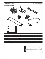
Страница 43: ...ural Propane 1 Junction Box 1 26D2128K 26D2128K 2 Large Glass Assy 1 42D0364K 42D0366K Peninsula See through 2 Large Glass Assy 1 42D0366K 42D0366K Corner Left Corner Right 3 Small Glass Assy 1 42D036...

Страница 44: ...1D0048 41D0048 5 Piezo Igniter 1 14D0503 14D0503 6 Injector 1 37D0362 37D0362 7 Burner Assy 1 42D0351 42D0351 8 Wire Assy Female 1 44D0500 44D0500 8 Wire Assy Male 1 44D0501 44D0501 Accessories 9 Ther...

Страница 45: ...17 2 Pilot Assy 1 37D0020 37D0021 3 Flexhose w Shut off Valve 1 69D0030 69D0030 4 Rocker Switch 1 41D0048 41D0048 5 Injector 1 37D0362 37D0349 6 Burner Assy 1 42D0351 42D0351 7 Wire Assy 1 54D2001 54D...

Страница 46: ...90 Elbow and BHSTK 11 x 14B Adjustable Pipe 1 1 Horizontal Flexible Pipe Termination Kit w Horizontal Termination Cap w BHSFTK Built in Vinyl Siding Standoff Heat Deflector Firestop 20 to 40 Flexible...

Страница 47: ...53D0419 Designer Series Gas Fireplaces 47...

Страница 48: ...48 53D0419 Designer Series Gas Fireplaces...

Страница 49: ...53D0419 Designer Series Gas Fireplaces 49...

Страница 50: ...omply with the above requirements provided however that during said thirty 30 day period a battery operated carbon monoxide detector with an alarm shall be installed Massachusetts Residents Only Pleas...

Страница 51: ...ifetime Warranty will also be void if the appliance is not operated and maintained according to the operating instructions supplied with the appliance and does not extend to 1 firebox burner assembly...

Страница 52: ...s Model EnerGuide Ratings Fireplace Efficiency STDVDNV 62 8 PFDVDNV 62 8 CRDVDNV 62 8 CLDVDNV 62 8 STDVDPV 70 6 PFDVDNV 70 6 CRDVDPV 70 6 CLDVDPV 70 6 STDVDNE 65 1 PFDVDNE 65 1 CRDVDNE 65 1 CLDVDNE 65...

Отзывы: