3
Interface description
Unit:mm
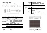
Take MISCOM8028-4GF as a example:
1. Indicator lights
5. Relay alarm output terminal
2. Console port
6. Power input terminal
3. 100M RJ45 port
7. Ground screw
4. Gigabit SFP port
8. Rack mounting ears
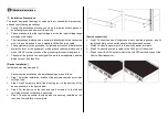
[Connect the power]
The switch supports AD220V single power input, using 5-position locking
terminals with 5.08mm pitch.
Number
Pin definition
1
Power 1 Input V1+(AC-L)/Positive(DC)
2
Power 1 Input V1-(AC-N)/Negative (DC)
3
Grounded
4
Power 2 Input V2+(AC-L)/Positive(DC)
5
Power 2 Input V2-(AC-N)/Negative (DC)
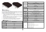
[Connect to the relay]
This series of switches supports the relay alarm function, and the wiring
terminals use 3-position 5.08mm pitch terminals. This relay is a normally
open and a normally closed relay, the middle one is the common terminal, the
left two terminals are normally open relays, and the right two terminals are
normally closed relays. When the switch is working normally, the normally
open relay is powered and closed, and the normally closed relay is
disconnected. The recommended switching load capacity of the relay is 1A
(24VDC).
Number
Pin definition
1
Alarm relay output normally open
2
Alarm relay output common terminal
3
Alarm relay output normally closed


