background image

25


BA082201-en 


8


Operation 


CAUTION 


Risk of personal injury and property damage 


Before each lifting procedure, check whether the running gear of the axle jack is 
correctly placed. 


It is the operator’s responsibility to make sure that operation represents no 
danger to persons. 


The axle jack is to be used as lifting device only. Never transport the load using 
the axle jack. 


Before working on the vehicle, lower the axle jack to nearest safety notch.  


When lifting a vehicle with two axle jack units, they must have a minimum sepa-
ration of 0.85 m. 


8.1


Operation of AL II 2.0 / 2.6 

Raising 

1  Use the pump lever. 

2  After reaching the desired lifting height, turn the left-hand lever to the right to 

lower the axle jack to the nearest safety notch.  

Lowering 

1  Slightly raise the axle jack to release the safety lock. 

2  Turn both hand levers to the left. 

 Left-hand lever is used for operating the trigger valve, right-hand lever for 

release of safety lock. Both levers return to the original position after release. 

8.2


Operation of AL II 2.0 PH / 2.6 PH / 4.0 PH 

Raising 

1  Turn the left-hand lever to the left. 

2  After reaching the desired lifting height, turn the left-hand lever to the right to 

lower the axle jack to the nearest safety notch. 

Lowering 

1  Slightly raise the axle jack to release the safety lock. 

2  Turn both hand levers to the left. 

 Left-hand lever is used for operating the trigger valve, right-hand lever for 

release of safety lock. Both levers return to the original position after release. 


Содержание AL II Series

Страница 1: ...r Kein Text mit angegebener Formatvorlage im Dokument Fehler Kein Text mit angegebener Formatvorlage im Dokument AL II Axle Jack Original Operating Instructions BA082201 en AL II 2 0 AL II 2 0 PH AL I...

Страница 2: ...e event of the grant of a patent utility model or design The contents of this edition have been checked with great care However errors cannot be fully excluded Sub ject to technical change without not...

Страница 3: ...hat to Do in the Event of an Accident 8 2 Transport and Storage 9 3 Installation and Initial Operation 9 4 Specifications 10 5 Installation Position 11 6 Installation Options 11 6 1 Installing the Wit...

Страница 4: ...Usage 26 9 Maintenance 27 9 1 Maintenance Schedule 27 9 2 Annual Inspection 28 9 3 Care Instructions 28 9 4 Refilling with Hydraulic Fluid 29 9 5 Troubleshooting 29 9 6 Spare Parts 29 9 7 Hydraulic D...

Страница 5: ...ords 1 2 1 Personal Injury DANGER indicates an immediate hazard which if not avoided will result in death or severe personal injury WARNING indicates a potential hazard which if not avoided could resu...

Страница 6: ...supports Usage as mobile work platform or for other lifting operations 1 5 Requirements on Operating and Service Personnel WARNING All persons employed in the operation maintenance installation remov...

Страница 7: ...ecure contact Make sure the vehicle doors are closed during raising and lowering cycles Closely watch axle jack and vehicle during raising and lowering cycles Before each lifting procedure check wheth...

Страница 8: ...lothing immediately Inhalation If symptoms persist seek medical treatment Skin contact Wash skin immediately with soap and water If skin irritation per sists seek immediate medical advice Eye contact...

Страница 9: ...properly so that they cannot fall taking into account size weight and the centre of gravity Store the packages in a covered area protected from direct sunlight at a low humidity and with temperatures...

Страница 10: ...min max 8 5 12 bar Full travel 250 mm 250 mm Minimum air flow 500 l min Load capacity 2600 kg 2600 kg Protrusion above runway max 70 mm 70 mm AL II 2 6 PH W 2 6 PH S 4 0 PH Extension length min max 9...

Страница 11: ...in longitudinal direction C Drill holes in side part of Lift top 6 Installation Options When the axle lift is in park position the spiral hose must be contracted in order to be strain relieved Ingrou...

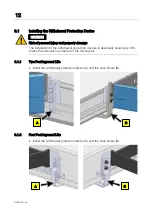
Страница 12: ...ation of the withdrawal protection devices is absolutely necessary Oth erwise the axle jack may fall out of the running rail 6 1 1 Two Post Inground Lifts Install the withdrawal protection device A an...

Страница 13: ...13 BA082201 en 6 1 3 DUO Install the withdrawal protection device A and the hose fixture B 6 1 4 CARLIFT Install the withdrawal protection devices four angles per axle jack as shown A B...

Страница 14: ...damage Make sure that the spiral hose is installed without kinks 6 2 1 Two Post Inground Lifts Slide the spiral hose A over the wire rope B Tension the wire rope using the ring bolt C Fasten the hose...

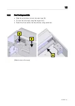
Страница 15: ...1 en 6 2 2 Four Post Inground Lifts Slide the spiral hose A over the wire rope B Tension the wire rope using the ring bolt C Fasten the hose end to the hose fixture using cable ties Bottom view of run...

Страница 16: ...16 BA082201 en 6 2 3 DUO Slide the spiral hose A over the wire rope B Tension the wire rope using the ring bolt C Fasten the hose end to the hose fixture using cable ties A C B...

Страница 17: ...17 BA082201 en 6 2 4 CARLIFT Slide the spiral hose A over the wire rope B Tension the wire rope using the ring bolt C Fasten the hose end to the hose fixture using cable ties A B C...

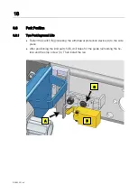
Страница 18: ...Post Inground Lifts Fasten the switch flag including the withdrawal protection device A to the side piece After positioning the limit switch B drill holes for the guide rail holding the fix ture and t...

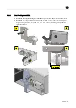
Страница 19: ...stop A including the withdrawal protection device to the side piece Install the lock B and the limit switch C to the runway Then install the prox imity switch D with a distance of 2 to 4 mm to the sw...

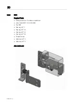
Страница 20: ...3 3 DUO Required Tools Drilling machine Cordless screwdriver Core hole drill 5 mm for M6 Tap M6 Hex key A F 7 Hex key A F 10 Hex key A F 13 Hex key A F 18 Thread locker Allen key A F 3 Allen key A F...

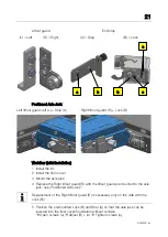
Страница 21: ...loor cover 3 Mount the axle jack 4 Replace the Right liftout guard R with the liftout guard premounted to the axle jack see Positioned Axle Jack Replacement of the Right liftout guard R is necessary o...

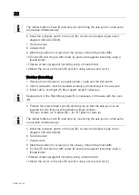
Страница 22: ...lly symmetrically to the axle jack 3 Install Left L and Right R liftout guard swap if necessary Replacement of the Right liftout guard R is necessary on the side with the Lock B 4 Position the premoun...

Страница 23: ...so that the axle jack is at the desired height There are multiple choices for flange and roller axle mounting The height can be varied by 12 5 mm by turning the black extensions in the axle jack Fig A...

Страница 24: ...24 BA082201 en A B C...

Страница 25: ...ght turn the left hand lever to the right to lower the axle jack to the nearest safety notch Lowering 1 Slightly raise the axle jack to release the safety lock 2 Turn both hand levers to the left Left...

Страница 26: ...en axle jack reaches preset height Height can be set by adjusting the corresponding valve Manual Lowering 1 Turn both operating handles in a counterclockwise direction Unloaded arms are retracted auto...

Страница 27: ...and supports Visual check Monthly Mechanical parts Grease all mechanical parts 3 months Hydraulic system Check fluid reservoir and top up if nec essary Check hydraulic system for leakage Check condit...

Страница 28: ...authorized and trained service techni cians provided by the manufacturer licensed dealers or service partners In case of non compliance the manufacturer s warranty becomes void 9 3 Care Instructions...

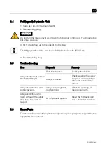
Страница 29: ...or Diagnosis Remedy Axle jack does not raise to the desired height Fluid level too low Re fill hydraulic fluid Axle jack locked Check whether the safety stop lever is in neutral po sition and can be f...

Страница 30: ...30 BA082201 en 9 7 Hydraulic Diagram AL II 2 0 2 6 AL II 2 0 PH 2 6 PH 4 0 PH...

Страница 31: ...87490 Haldenwang Germany Phone 49 0 8374 585 0 Fax 49 0 8374 585 500 Email info maha de Alternatively you may take the equipment to a specialised waste management plant to ensure that all components...

Отзывы: