background image

14

Magtrol Model 6530 Three-Phase Power Analyzer

Chapter 3 – Installation/Configuration

SETUP

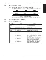
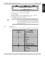
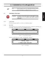
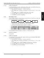
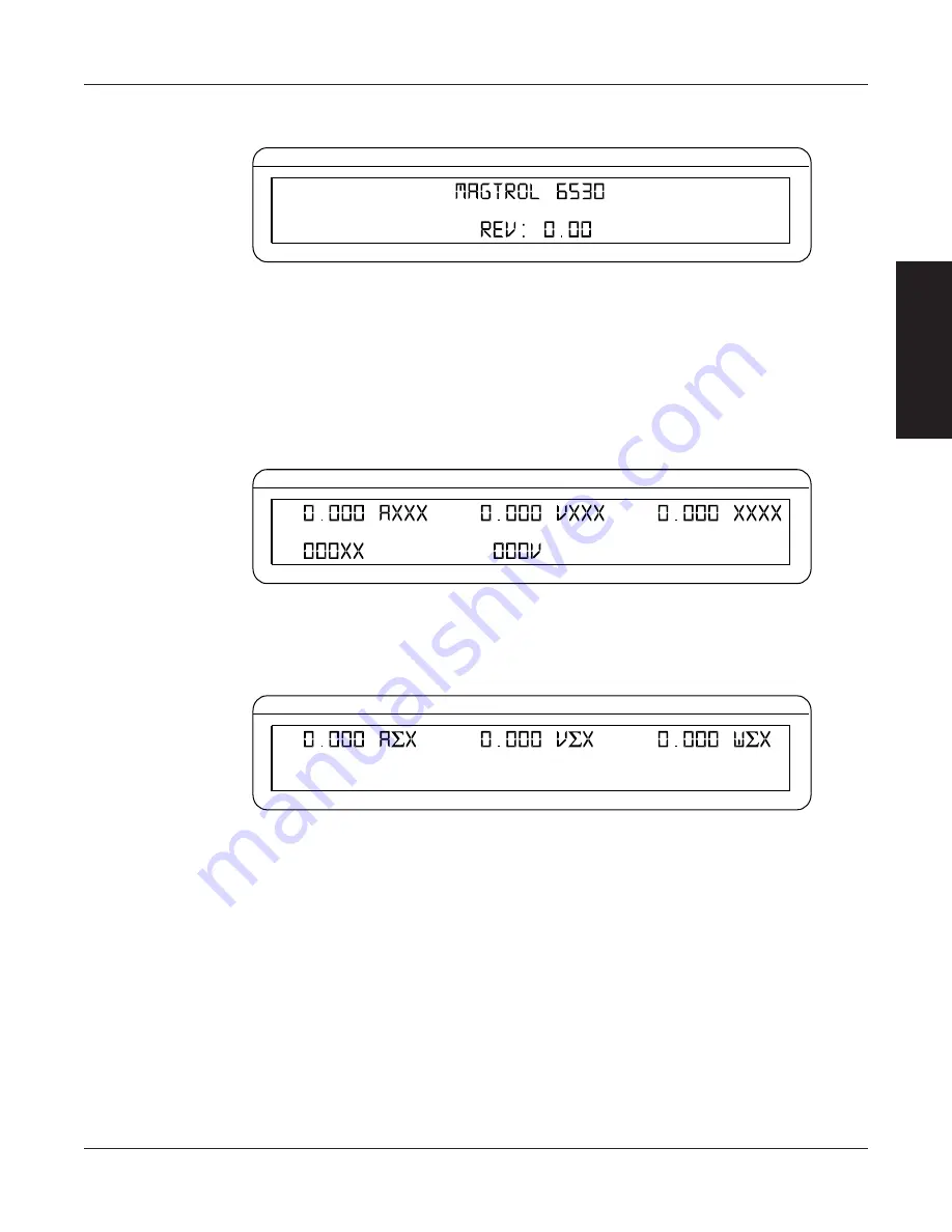
Then an additional display will appear indicating the version of your Magtrol 6530 Power Analyzer.

CURRENT

VOLTAGE

POWER/PF

Figure 3–3  Revision Display

3.1.3

M

AIN

 M

ENU

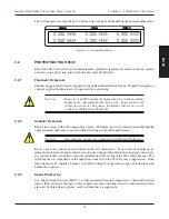
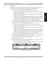
When the 6530 is completely powered up and ready for use, the main menu will appear on the
display.  The main menu is defined by the last configuration that was used.  This could include one
of three different menus:  phase, summation or custom.

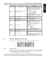
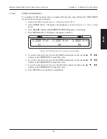
The phase menu could be a representation of phase 1, 2 or 3 and will appear as follows.

CURRENT

VOLTAGE

POWER/PF

Figure 3–4  Phase Main Menu

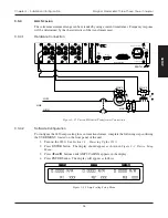
The summation menu contains information pertaining to all 3 phases.  The voltage value represents
an average of the 3 phases and the amps and watts values represent the sum of the phases.

CURRENT

VOLTAGE

POWER/PF

Figure 3–5  Summation Main Menu

Содержание 6530

Страница 1: ...Model 6530 Three Phase Power Analyzer User s Manual...

Страница 2: ...result from the use of the information contained within this publication COPYRIGHT Copyright 2001 2003 Magtrol Inc All rights reserved Copying or reproduction of all or any part of the contents of thi...

Страница 3: ...Securely ground the 6530 Power Analyzer case by connecting a good earth ground at the ground stud located on the rear panel of the unit Use a number 12 AWG or larger wire 3 Check line voltage before...

Страница 4: ...m r o f n i n o i t p o t u p t u o g o l a n a d e d d A 3 1 2 0 0 2 5 0 A v e R n o i t i d E t s 1 c i h p a r g u n e M p u t e S r o t c a F e l a c S r o s n e S l a n r e t x E n i V m A o t A...

Страница 5: ...1 Enabling Secondary Functions 6 2 2 2 Using Front Panel Controls and Buttons 6 2 3 VACUUM FLUORESCENT DISPLAY VFD 8 2 3 1 Contrast Settings 8 2 3 2 Display Guide 9 2 4 REAR PANEL 10 2 5 REAR PANEL IN...

Страница 6: ...onnector Cable 42 5 1 2 Changing the GPIB Primary Address 42 5 2 ABOUT THE RS 232 INTERFACE 43 5 2 1 Connection 43 5 2 2 Communication Parameters 44 5 2 3 Baud Rate 44 5 3 CHECKING THE 6530 TO PC CONN...

Страница 7: ...SHOOTING 58 APPENDIX A SCHEMATICS 59 A 1 MAIN BOARD DSP RAM FLASH 59 A 2 MAIN BOARD INPUT OUTPUT GPIB RS 232 60 A 3 MAIN BOARD FPGA 61 A 4 INPUT MODULE CURRENT 62 A 5 INPUT MODULE VOLTAGE 63 A 6 KEY P...

Страница 8: ...5 Three Phase Four Wire Wiring Connection 21 Figure 3 16 Three Voltage Three Ampere Wiring Schematic 22 Figure 3 17 Three Voltage Three Ampere Wiring Connection 22 Figure 3 18 Sensor Substitution Wiri...

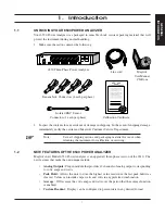
Страница 9: ...alyzer which describes the unit and provides its mechanical and electrical characteristics Chapter 2 CONTROLS Description of the elements located on the front and rear panels of the unit Chapter 3 INS...

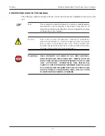
Страница 10: ...AUTION THIS IS USED TO DRAW THE OPERATOR S ATTENTION TO INFORMATION DIRECTIVES PROCEDURES ETC WHICH IF IGNORED MAY RESULT IN DAMAGE BEING CAUSED TO THE MATERIAL BEING USED THE ASSOCIATED TEXT DESCRIBE...

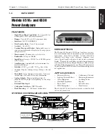
Страница 11: ...to store the highest value read since the last peak hold was cleared Values can include amps watts and volts in any preferred combination Average Will average the volts amps and watts over the period...

Страница 12: ...PLIANCES ALLASTS RIVES ETC E 3 0 3 0 7 2 9 2 4 2 0 3 0 7 2 9 2 NPUT 0OWER 30 YNAMOMETER ONTROLLER 5 4 0 5 4 6 6 6 6 84 39 24 2 5 6 Z 53 X MM 54 5 0 53 6 5 3 M 6 3 6 M 6 4 23 0 42 03 6 6 43 8 84 8 6 8...

Страница 13: ...0EAK OLD NRUSH 6OLT 2EADINGS 2 3 0EAK REST ACTOR AND 0EAK OLD NRUSH 0HASE AND 3UMMATION ATA 2 4 0 2 2 0 3 3 7IDTH IN MM EIGHT IN MM EPTH WITH HANDLES IN IN MM MM 7EIGHT LB KG 2 15 9 3OURCE 6 6 6 OR 84...

Страница 14: ...HREE 0HASE 0OWER NALYZER 4HREE 0HASE 0OWER NALYZER WITH NALOG UTPUT PTION ESCRIPTION 4HE NALOG UTPUT IS A PLUG IN MODULE DESIGNED SPECIFICALLY FOR USE WITH THE E 3INGLE 0HASE 0OWER NALYZER AND 4HREE 0...

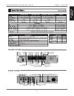
Страница 15: ...Power switch Ten double function control buttons n o i t c n u F y r a m i r P n o i t c n u F y r a d n o c e S E S A H P Y A L P S I D T E G N A R T N E R R U C t n e r r u c C D S E G N A R T N E R...

Страница 16: ...b a e u l b n i n e t t i r w n o i t c n u f e h t s e l b a n E n o t t u b l o r t n o c u n e M r e s U R E T N E n o t t u b s i h t s s e r P U N E M R E S U s e l b a s i D s e l b a n E W n o...

Страница 17: ...a k p x A d e r u s a e m g n i e b e s a h p x e r e h w e g n a R t n e r r u C T n o t t u b s i h t s s e r P e g n a r s p m a s t n e m e r c e D S n o t t u b s i h t s s e r P e g n a r s p m...

Страница 18: ...e S d e y a l p s i d e h t d n a F P A V W s s e r p o t e u n i t n o C e h t h g u o r h t e l g g o t s e u l a v d e y a l p s i d g n i w o l l o f x W s t t a w h s u r n i s t t a w x W V x A...

Страница 19: ...sure the lowest possible setting is used to achieve desired result Using a setting higher than necessary may cause display segments to burn in over a period of time resulting in uneven illumination f...

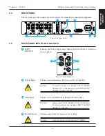
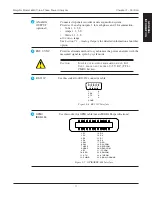
Страница 20: ...sor Alternate amps input for current sensor or shunt CAUTION VOLTAGE SHOULD NOT EXCEED 10 V AC DC Contains the Voltage Input Amps Input and External Sensor connectors for each phase 2 4 REAR PANEL The...

Страница 21: ...asured signal in cycle by cycle mode CAUTION INPUT IS NOT ISOLATED FROM EARTH GROUND EXT SYNC SHOULD NOT EXCEED 0 5 V DC TTL CMOS LEVELS RS 232C Use this socket for RS 232 connector cable 5 GND 1 6 9...

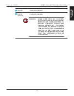
Страница 22: ...AGTROL DYNAMOMETERS AND ELECTRONIC PRODUCTS ARE EARTH GROUNDED TO ENSURE PERSONAL SAFETY AND PROPER OPERATION SECURELY GROUND THE 6530 POWER ANALYZER CASE BY CONNECTING A GOOD EARTH GROUND AT THE GROU...

Страница 23: ...DED BEFORE STARTING 3 1 1 LINE VOLTAGE The 6530 will operate from 85 to 264 VAC on a 50 60 Hz line voltage 3 1 2 SELF TEST After turning the power on to the 6530 the display panel will show all segmen...

Страница 24: ...ear on the display The main menu is defined by the last configuration that was used This could include one of three different menus phase summation or custom The phase menu could be a representation o...

Страница 25: ...3 2 2 CURRENT OVERLOAD There are no fuses in the 6530 measuring circuits Therefore excessive current passed through the amps terminals will cause excessive internal heating and possible unit damage CA...

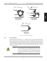
Страница 26: ...ment accuracy by eliminating line voltage drop from the power measurement For safety an overload circuit breaker removes all load voltage during an over current condition The voltage sense lines are c...

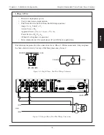
Страница 27: ...there are a number of different ways in which the unit can be wired 3 3 1 1 Hardware Connections The wiring mode selections include 1 Phase 2 Wire 1 Phase 3 Wire 3 Phase 3 Wire 3 Phase 4 Wire 3 Volt...

Страница 28: ...ase 2 Wire measurement Only one phase has been shown for clarity but any of the three phases may be used 1 2 3 LOAD V A A V SOURCE LOAD SOURCE A V Figure 3 8 Single Phase Two Wire Wiring Schematic LIN...

Страница 29: ...otice that only phase one and three are used 3 1 LOAD SOURCE V A A V V 1 3 1 N V LOAD A 3 A SOURCE N L1 L2 A V A V Figure 3 10 Single Phase Three Wire Wiring Schematic A N A L O G O U T P U T A V V V...

Страница 30: ...otice that only phase one and three are used LOAD S T A 3 V V V 1 R SOURCE 3 A A V LOAD SOURCE R S T 3 1 A V A V A1 Figure 3 12 Three Phase Three Wire Wiring Schematic MOV LOAD MOV MOV LOAD LOAD 2 3 1...

Страница 31: ...ire measurement LOAD V V1 V R T S A V 3 SOURCE A A 2 V 2 V A 3 A LOAD N T R S SOURCE 2 3 1 A V A V A V A1 Figure 3 14 Three Phase Four Wire Wiring Schematic 3 2 1 NEUTRAL CB MOV LOAD MOV MOV LOAD LOAD...

Страница 32: ...ections for a 3 Volt 3 Amp measurement 2 3 1 V1 V 2 V V A A2 A1 T S A R LOAD SOURCE LOAD SOURCE R S T V A 3 3 A V A V A V A V Figure 3 16 Three Voltage Three Ampere Wiring Schematic 3 2 1 EARTH CB MOV...

Страница 33: ...frequency Measured Value Value Filter Square Root Selections include 1 Hz 2 Hz 5 Hz 10 Hz 20 Hz 50 Hz and 100 Hz Correlation between filter setting and response is as follows g n i t t e S r e t l i...

Страница 34: ...COAXIAL CABLE A A A A A V Figure 3 18 Sensor Substitution Wiring Schematic A N A L O G O U T P U T A V V V A V A EXT SYNC EARTH GROUND 20VA 50 60Hz FUSE 5x20mm CAUTION DOUBLE POLE FUSING 120V UL CSA 2...

Страница 35: ...Press and buttons until EXTERNAL SENSOR appears in the display 4 Press ENTER button The display will appear as follows CURRENT VOLTAGE POWER PF Figure 3 20 External Sensor Scale Factor Setup Menu 5 To...

Страница 36: ...NC 20 A AMPS 750 V VOLTS MAX EXT MAX 1000 V MAX MAX 10 V SENSOR 20 A AMPS 750 V VOLTS MAX EXT MAX 1000 V MAX MAX 10 V SENSOR 20 A AMPS 750 V VOLTS MAX EXT MAX 1000 V MAX MAX 10 V SENSOR Figure 3 21 Cu...

Страница 37: ...in the USER MENU to adjust the value 8 To turn phase 2 scaling ON press the PEAK CF button under OFF until ON is reached 9 To set the amp scaling for phase 3 press the AVG button under A3 and use the...

Страница 38: ...isplay 4 Press ENTER button The display will appear as follows CURRENT VOLTAGE POWER PF Figure 3 24 Volt Scaling Setup Menu 5 To set the volt scaling for phase 1 press the RMS button under V1 and use...

Страница 39: ...ternal sensor and 1 A 5 A 10 A and 20 A when using amps input 4 Select voltage measurement mode DC RMS peak crest factor or peak hold a To select DC press SHIFT and release then press DC button locate...

Страница 40: ...HOLD button The display will appear as follows indicating that the hold function is enabled CURRENT VOLTAGE POWER PF HOLD MODE INDICATORS Figure 3 26 Hold Mode To disable press and release HOLD butto...

Страница 41: ...configured to present data in any format To set press SHIFT button and release then press DISPLAY The display will appear as follows CURRENT VOLTAGE POWER PF Figure 3 29 Custom Display There are 6 fi...

Страница 42: ...analog to digital converter The part accepts an input signal of 1 25 volts centered on a 2 5 VDC volt bias The chart below shows system input at 10 and 100 of range e g n a R C D V n I s t l o V l a t...

Страница 43: ...The chart below shows system input at 10 and 100 of range e g n a R n I s p m A C D A s t l o V t n u h S e g a t S t s r i F p m A n i a G D A t a s t l o V t u p n I s t i B p m a 1 1 0 2 1 0 0 0 4...

Страница 44: ...5 0 0 0 0 0 5 7 6 9 4 8 4 0 0 8 6 2 1 V m 0 5 0 5 0 0 0 0 5 7 6 9 8 3 8 4 0 1 8 6 2 1 V m 0 5 2 5 2 0 0 0 5 5 3 9 1 4 8 4 0 0 8 6 2 1 V m 0 5 2 0 5 2 0 0 5 5 3 9 1 9 3 8 4 0 4 8 6 2 1 V m 0 0 5 0 5 0...

Страница 45: ...input is read and checked for an over range condition The offset is then added to the reading and the reading is negated and saved The volt reading is checked to see if it is the peak and if so is st...

Страница 46: ...rcular buffer Add 2cd V buffer contents and divide by 32 Save this value Add 2cd I buffer contents and divide by 32 Save this value Add 2cd VI buffer contents and divide by 32 Save this value Each sam...

Страница 47: ...egated and saved The amps input is read and checked for an over range condition The offset is then added to the reading and the reading is negated and saved The volt reading is checked to see if it is...

Страница 48: ...2 word circular buffer Add 2cd V2 buffer contents and divide by 32 Save this value Add 2cd I2 buffer contents and divide by 32 Save this value Add 2cd VI buffer contents and divide by 32 Save this val...

Страница 49: ...0 000000 0 0003357 Square of 56 bit 00 000000 F20000 0 00000012269 Store to 24 bit 000000 0 0000000 Example 2 A D reading 000C 56 bit register 00 000C00 000000 0 0003662 Square of 56 bit 00 000001 200...

Страница 50: ...ction 3 3 7 3 Peak Hold The graph below shows the current draw from a 1 3 horsepower motor during initial startup At startup the current inrush peaks at about 14 amps then settles to 4 25 amps When th...

Страница 51: ...ete cycle of the incoming waveform The measurements are valid from 20 Hz to 500 Hz The power analyzer may be synchronized from any of the phase volts or amps inputs the line voltage or the back panel...

Страница 52: ...o be installed between the computer and the 6530 Magtrol recommends National Instruments Corporation hardware and software 5 1 1 INSTALLING THE GPIB IEEE 488 CONNECTOR CABLE CAUTION MAKE SURE BOTH THE...

Страница 53: ...esired primary address is reached range 0 15 6 Press ENTER to return to main menu 5 2 ABOUT THE RS 232 INTERFACE The 6530 is equipped with an RS 232 serial interface that communicates with the host co...

Страница 54: ...CURRENT VOLTAGE POWER PF Figure 5 5 RS 232 Baud Rate Setup Menu 5 Use the and buttons until desired baud rate is reached 6 Press ENTER to return to main menu 5 3 CHECKING THE 6530 TO PC CONNECTION No...

Страница 55: ...f e h t n i d e t a c o l s i e c a p s a f I e d a m e b o t d e e n s e g n a h c o n d n a e g n a r n i h t i w s i l a n g i s t u p n i Sections 5 4 1 through 5 4 3 contain return data format e...

Страница 56: ...14 measurement value float E notation ANSI 5 4 3 1 Good Response s s1 19494E 02 r n 5 4 3 2 Over Range Condition s4 94796E 01 r n 5 5 PROGRAMMING Note Check the manual provided with your software for...

Страница 57: ...s p m a e h t r o f e d o m e s a h p t u p n i e h t s e t a c i d n i 1 m e r a 1 m r o f s e u l a V s e s a h p l l a 0 1 e s a h p 1 2 e s a h p 2 3 e s a h p 3 o t u a s i e d o m e g n a r r e...

Страница 58: ...l c y c r e t l i f t n e m e r u s a e m e h t r e h t e h w s e t a c i d n i m c i l c y c r o s u o u n i t n o c s i e d o m e r a m r o f s e u l a V s u o u n i t n o c 0 e l c y c y b e l c y...

Страница 59: ...t a c i d n i 1 m e r a 1 m r o f s e u l a V s e s a h p l l a 0 1 e s a h p 1 2 e s a h p 2 3 e s a h p 3 t n a t s n o c g n i l a c s e g a t l o v e h t s e t a c i d n i 2 m g n i w o l l o f e...

Страница 60: ...l a m r o n 0 t n e m e r u s a e m n o g n i d n e p e d g n i t t e s e d o m s u o e n a t n a t s n i k a e p 1 r o t c a f t s e r c 2 3 C D S M R h s u r n i d l o h k a e p r o t a n i m r e t...

Страница 61: ...s i n o i t a r b i l a c o r e z t u p n i n o e r a t i n u e h t 0 n a h t r e t a e r g s i 2 m n e h W d n a d e t s e u q e r s i n o i t a r b i l a c n i a g s e m u s s a t u p n i n o e r a...

Страница 62: ...EQUIVALENT FLUKE 5700A OR VOLTAGE CALIBRATOR EQUIVALENT FLUKE 5100A OR FLUKE 5700A OR VOLTAGE CALIBRATOR EQUIVALENT GUILDLINE 7620A OR FLUKE 5725A 5205A TRANSCONDUCTANCE AMP OPTIONAL FOR AMPS 2 Figur...

Страница 63: ...A0 xx xx Where xx xx is the voltage current on the inputs full scale 10 Repeat steps 5 through 9 for all ranges 11 Remove amp and voltage inputs 12 Attach external input to calibrator voltage 13 Set a...

Страница 64: ...og output scaling values are set from the front panel Amp volt and watt scaling values correspond to units per analog output volts units output volt displayed measurement value output volts Examples 1...

Страница 65: ...over plate associated with that connector Remove the cover plate by removing the two screws 7 Slip the analog output board through the back of the unit and plug it into J3 AUX2 8 Using the screws remo...

Страница 66: ...r the analog output The advantage of closed box calibration is that the user does not have to disassemble the case or make mechanical adjustments 7 1 5 2 Calibration Schedule Calibrate the 6530 analog...

Страница 67: ...n i 1 m l e n n a h c A D d e r u s a e m e h t s e t a c i d n i 2 m l l u f e v i t a g e n r o e v i t i s o p e g a t l o v t u p t u o e d o m n o i t a r b i l a c n o g n i d n e p e d e l a c...

Страница 68: ...s e r d d a B I P G r e z y l a n a e b d l u o h s e l b a c B I P G o t d e h c a t t a d n a g n i n o i t c n u f r e t u p m o c d n a r e z y l a n a r e w o p d r a c e c a f r e t n i n o i t...

Страница 69: ...A12 20 A11 19 A10 18 A9 17 A8 16 A7 15 A6 14 A5 13 A4 4 A3 3 A2 2 A1 1 A0 C23 0 1uF C16 0 01uF C15 0 1uF C20 0 01uF C19 0 1uF C22 0 01uF C21 0 1uF C32 0 01uF C34 0 1uF C25 0 01uF C26 0 1uF C12 0 01uF...

Страница 70: ...7 5 3 1 C55 0 1uF C62 0 1uF C64 0 1uF C63 0 1uF R18 10k D6 D1N914 U14 TNT4882 20 ABUS_OEN 1 BBUS_OEN 51 DCAS 23 TRIG 28 REM 66 LADCS 21 TADCS 100 KEYRSTN 99 KEYDQ 98 KEYCLKN 96 XTAL1 95 XTAL0 76 SRQN...

Страница 71: ...6 133 I O105 132 I O104 131 I O103 130 I O102 129 I O101 126 I O100 125 I O99 124 I O98 123 I O97 122 I O96 121 I O95 120 I O94 119 I O93 117 I O92 116 I O91 115 I O90 114 I O89 113 I O88 112 I O87 PG...

Страница 72: ...2 1 U17 PS2701 1 4 3 2 1 U12 PS2701 1 4 3 2 1 U13 HCPL0720 5 6 8 4 2 1 U15 PS9711 3 4 5 2 1 U7 REF192FS 4 GND 6 VOUT 3 SHTDWN 2 V J2 DIN20_PLUG B10 B9 B8 B7 B6 B5 B4 B3 B2 B1 A10 A9 A8 A7 A6 A5 A4 A3...

Страница 73: ...GND DB13 32 DGND DB14 31 DGND DB15 29 CS 5 DVAL RD 6 DGND1 28 DGND 26 AGND7 25 AGND6 21 AGND5 19 AGND4 15 AGND3 13 AGND2 10 AGND1 9 AGND 11 CLKIN 12 XTAL 17 RESET 30 SYNC 27 CAL 7 UNI 24 REF2 22 REF1...

Страница 74: ...64 Magtrol Model 6530 Power Analyzer Appendix A Schematics APPENDICES A 6 KEY PAD...

Страница 75: ...C5 0 1 C1 0 1 C9 0 1 C2 0 1 C13 1OuF AGND DGND2 J2 A1 J2 A2 J2 A3 J2 A4 J2 A5 J2 A6 J2 A7 J2 A8 J2 A9 J2 A10 J2 B1 J2 B2 J2 B3 J2 B4 J2 B5 J2 B6 J2 B7 J2 B8 J2 B9 J2 B10 SC10 SC11 SC12 C16 1 C15 10uF...

Страница 76: ...S R37 499 15VA 15VA 2 3 1 D4 BAT54S R24 10k R25 10k C25 0 01 15VA 15VA 14 11 12 13 4 U5 D LT2079 R27 10k R26 10k C24 0 01 8 10 9 U5 C LT2079 R20 10k R19 10k C23 0 01 7 5 6 U5 B LT2079 R18 10k 1 3 2 U5...

Страница 77: ...54S R42 499 15VA 15VA 2 3 1 D8 BAT54S R9 10k R10 10k C29 0 01 15VA 15VA 14 11 12 13 4 U1 D LT2079 R12 10k R11 10k C28 0 01 8 10 9 U1 C LT2079 R4 10k R3 10k C27 0 01 7 5 6 U1 B LT2079 R2 10k 1 3 2 U1 A...

Страница 78: ...54S R46 499 15VA 15VA 2 3 1 D12 BAT54S R13 10k R14 10k C33 0 01 15VA 15VA 14 11 12 13 4 U2 D LT2079 R16 10k R15 10k C32 0 01 8 10 9 U2 C LT2079 R8 10k R7 10k C31 0 01 7 5 6 U2 B LT2079 R6 10k 1 3 2 U2...

Страница 79: ...st known for developing standards for the computer and electronics industry Inrush The initial current that is drawn when an electronic device is turned on The inrush current can be substantially high...

Страница 80: ...munication Parameters 44 Configuration Commands 47 Connection 6530 to PC 44 Analog Output Board 55 RS 232 43 Continuous Mode 41 Contrast Settings 8 Controls 5 6 Crest Factor 41 Current See also Amps C...

Страница 81: ...11 P Peak 39 Peak Hold 31 40 Phase Main Menu 14 Phase Setup 29 Primary Address 42 Programming 46 R Rear Panel 10 Remote Voltage Sense 16 RMS 41 69 Round Off Error 39 RS 232 Connection 43 RS 232 Inter...
Страница 82: ...ir service under this warranty purchaser must forward the product transportation prepaid and a description of the malfunction to the factory The instrument shall be repaired at the factory and returne...

Страница 83: ...14224 USA Phone 1 716 668 5555 Fax 1 716 668 8705 E mail magtrol magtrol com MAGTROL SA Route de Moncor 4B 1701 Fribourg Switzerland Phone 41 0 26 407 3000 Fax 41 0 26 407 3001 E mail magtrol magtrol...

Отзывы: