


24
Magtrol Model 6200 Open Loop Dynamometer Controller
Chapter 6 – Calibration
MAINTENANCE
1. Connect the chosen dynamometer to the 6200 using the 14-pin signal cable and the 2-pin
brake cable.
2. Attach the calibration beam to the dynamometer shaft.
3. Enter the calibration mode.
4. Press the bRAkE oN/oFF button oN to apply full loading to the dynamometer.
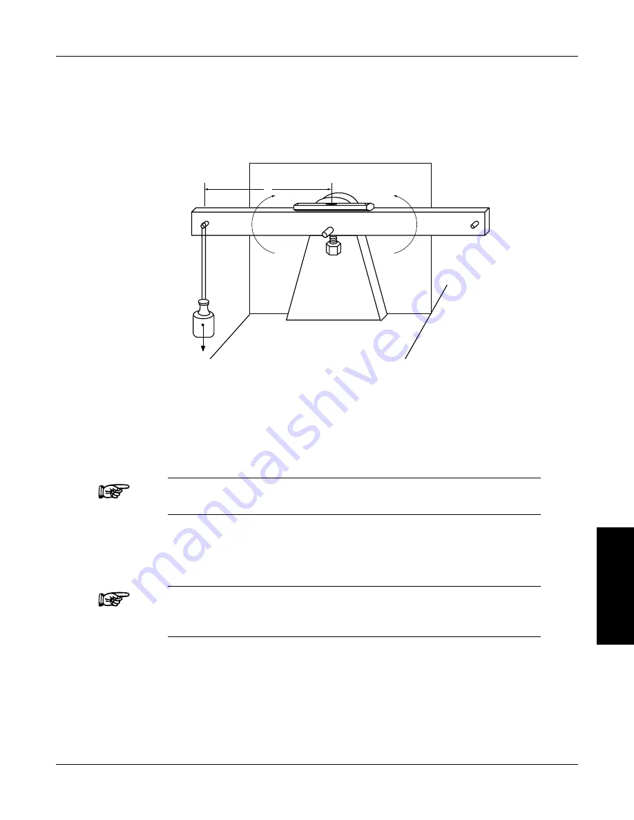
5. hang the weight on the calibration beam pin and level the beam as illustrated in the following
diagr
Torque = Weight (W) × Distance (D)
Weight (W) = Torque / Distance (D)
d
W
CW
CCW
t
t
Figure 6–1 Alternative Calibration
6. Press the DISPLAY button.
7. Adjust the gain by turning the Decrease/Increase Dial until the displayed voltage equals the
reference voltage.
Note:
The magnitude of change per revolution can be increased by pressing
the UP
button or decreased by pressing the DoWN
button.
8. Remove the weight for zERo adjustment.
9. Press the UNITS DISPLAY button.
10. Adjust the Increase/Decrease Dial until the display indicates 0 mVDC.
Note:
The mV output of the dynamometer will be equivalent to the Weight
times Distance on the calibration beam, disregarding any decimal
point.
example
Magtrol’s hD-400-6 Dynamometer has a full-scale torque of 40.0 oz·in. The distance
from the center of the dynamometer shaft to the pin on the calibration beam is 5 inches.
Placing an 8 oz. weight on the pin will produce a torque of 40.0 oz·in. The mV output of the
dynamometer will be equivalent to 8 oz. multiplied by 5 inches, yielding an output signal
of 400 mV.