Magtek ExpressCard 2000 Скачать руководство пользователя страница 9

3 - Power Supply Replacement Procedure 

ExpressCard 2000| Instant Issuance Card Personalization System | Power Supply Replacement Procedure 

 
Page 9 


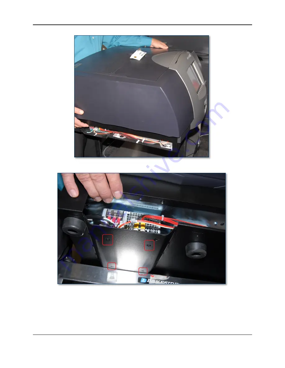
Figure 3-2 – One Person Keeps the Device Stable (LEFT VIEW) 


Figure 3-3 - Four Power Supply Screws Exposed (BOTTOM LEFT VIEW) 

5)


Locate the power supply on the rear left side of the device, behind the left side access door. 

Содержание ExpressCard 2000

Страница 1: ...0 I Phone 562 546 6400 I Technical Support 888 624 8350 www magtek com ExpressCard 2000 Instant Issuance Card Personalization System Power Supply Replacement Procedure September 22 2014 Manual Part Nu...

Страница 2: ...reproduced or transmitted in any form or by any means electronic or mechanical for any purpose without the express written permission of MagTek Inc MagTek is a registered trademark of MagTek Inc Magn...

Страница 3: ...cable electronic board or assembly SAFETY REQUIREMENTS Caution Never do any of the following DO NOT use a ground adapter plug to connect equipment to a power socket outlet that lacks a ground connect...

Страница 4: ...of Contents Table of Contents 4 1 Required Tools Materials and Documents 5 1 1 Required Tools 5 1 2 Suggested Tools 5 1 3 Required Materials 5 1 4 Suggested Materials 5 1 5 Required Software and Docu...

Страница 5: ...ashlight 1 3 Required Materials Part Number Quantity Description 33070941 1 ea ASM REPLACEMENT KIT POWER SUPPLY EC2000 1 4 Suggested Materials Part Number Quantity Description 33011009 1 ea ASM KIT ST...

Страница 6: ...ance functions so many of the cross references to deeper how to procedures from that manual have been removed for brevity The information in this document is intended for use by trained professional s...

Страница 7: ...es from the device including card stock image printer ribbons indent cartridges and tipper foils Some consumables contain negative imprints of cardholder data and must be handled securely 2 Make sure...

Страница 8: ...ple move the device then one person keeps the device stable while the other removes the power supply Figure 3 1 Power Supply FRONT LEFT VIEW FROM ABOVE To remove the power supply follow these steps 1...

Страница 9: ...Personalization System Power Supply Replacement Procedure Page 9 Figure 3 2 One Person Keeps the Device Stable LEFT VIEW Figure 3 3 Four Power Supply Screws Exposed BOTTOM LEFT VIEW 5 Locate the power...

Страница 10: ...LEFT SIDE VIEW 6 Remove the clear plastic cover that protects the power supply inputs 7 Use the No 2 Philips screwdriver to loosen the screws that secure the three power input wires to the power suppl...

Страница 11: ...ws holding the power supply output cables then disconnect the cables See Figure 3 7 Figure 3 7 Power Supply Output Cables LEFT VIEW 10 Use the No 2 screwdriver to remove the four screws on the bottom...

Страница 12: ...connect the output wires according to Figure 3 7 5 Plug in the control and monitoring cable 6 Re connect the input wires Insert the spade connectors behind the plate behind the screws not directly beh...

Отзывы: