background image

ADJUSTING BLADE TRACKING

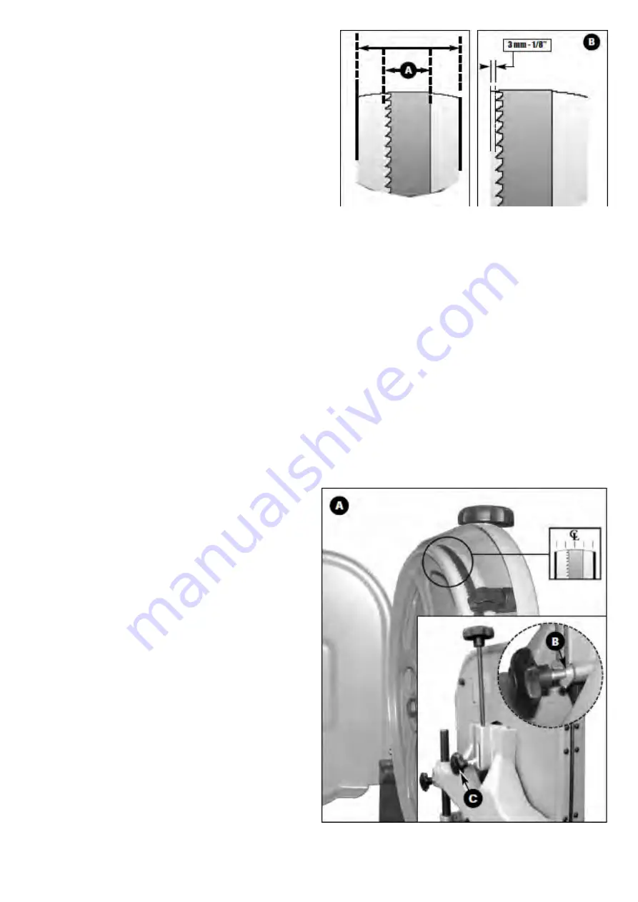
Blade tracking means centering the blade on the wheels A.

Ideally, the blade should stay relatively centered on both the

upper and lower wheels.

Due to natural variations in castings, blade thickness or density

and tire wear, absolute perfect centering alignment is

rarely attainable. A slight misalignment of the blade on the

wheels is inevitable and as long as it is kept to a minimum

(following the steps listed below) will not hinder the performance

of the saw.

This misalignment is controlled and kept to a minimum by adjusting the tilt angle of the upper wheel.

When adjusting blade tracking to center the blade on the wheels and assuming that perfect centering is not attainable,

it is preferable to have the blade slightly off-center towards the front of the wheels rather than towards the rear

because the teeth on most bandsaw blades have alternating hook (one inner, one outer) – therefore if the blade is

centered too far back on the wheel (or if the blade tension is too tight), inner hooked teeth will dig into the wheel

tire and cause premature wear of the tire.

Nonetheless, to avoid having the blade come off of the wheels on it’s own during operation, the front edge of the

blades teeth should never be any closer than 3 mm (1/8”) from the front edge of the wheel B.

BLADE CLEARANCE

Note: As previously stated, when performing blade installation, removal, tensioning or 

tracking, maximum clearance between the blade and both upper and lower bearing assemblies 

is required to minimize friction, which would be damaging to the blade. Refer back and follow 

the instructions for “blade clearance” before performing blade tracking adjustments.

To adjust the blade tracking:

1. Open the upper wheel cover door then rotate the wheel

    slowly forward by hand. The blade should remain as 

    centered as possible on the wheel as it turns A.

2. If the blade tracking must be adjusted, loosen thumb nut B, 

    then turn the tracking knob C, located on the rear of the 

    bandsaw: 

a) Clockwise if the blade moves toward the front of the wheel. 

     This tilts the top of the wheel to the back and moves the 

     blade toward the center.

b) Counter-clockwise if the blade moves toward the back 

    edge. This tilts the top of the wheel to the front and moves

    the blade toward the center.

Note: Turn the tracking knob in 1/2 turn 

increments, recheck and adjust again as 

needed.

3. Re-tighten thumb nut B

Содержание MI-91340

Страница 1: ...MODEL NO MI 91340 OPERATING MANUAL...

Страница 2: ...LOCK KNOB UPPER BLADE GUIDE ASSEMBLY BLADE GUARD MITER GAUGE TABLE ALIGNMENT PIN DUST PORT BASE CABINET TABLE TILT LOCK KNOB LOWER WHEEL COVER DOOR ON OFF SWITCH W SAFETY KEY UPPER WHEEL COVER DOOR BL...

Страница 3: ...mm Hex socket Feeler gauge set Combination square N T U V W X Y P Q R S G D E F H I O STAND ASSEMBLY J K K M C 8 QTY 1 W A S D N A B A 1 T R O P T S U D C 4 T L O B D A E H X E H D 8 R E H S A W T A...

Страница 4: ...ermine whether or not it is time to replace the blade It is not cutting as fast It is not able to follow a cutting line as it used to REPLACING THE UPPER AND LOWER THRUST BEARINGS 1 Turn the tension k...

Страница 5: ...aring back 1 Loosen the upper thumb screw D 2 Use the micro adjust nut E to move the thrust bearing F back as far as possible behind the blade Move the lower guide blocks thrust bearing away from the...

Страница 6: ...cking properly Adjust the upper and lower blade guides and thrust bearings after each blade tension and tracking adjustment Whenever the upper blade guide and thrust bearing are adjusted the lower bla...

Страница 7: ...wer blade guide blocks and thrust bearing perform the same function as the upper blade guide blocks and thrust bearing except they do so after the blade has contacted the stock being cut 1 Repeat step...

Страница 8: ...diameter circle that can be cut is determined by the width of the blade For example a 1 4 wide blade will cut a minimum diameter of approximately 1 1 2 PERIODIC MAINTENANCE LUBRICATION Disconnect mac...

Страница 9: ...sing 8 carriage bolts C and flange nuts D then tighten using a 12 mm open wrench 3 Attach the top plate to the left and right side panels using 4 carriage bolts C and flange nuts D as shown above Note...

Страница 10: ...dust collector not included Install the dust outlet on the right side of the bandsaw as follows 1 Open the lower wheel cover door 2 Using a 10 mm wrench attach the dust port to the edge of the door as...

Страница 11: ...wrench and the two hex bolts I and J using a 12 mm open wrench and 12 mm socket wrench 8 Re install the red insert to the center of the table with the opening in the slot facing the rear of the saw K...

Страница 12: ...e the table is still at 90 to the blade If not re adjust the table stop bolt Never adjust the table angle while the bandsaw is running Turn off power first 1 Loosen the two lock knobs A 2 Tilt the tab...

Страница 13: ...he tire Nonetheless to avoid having the blade come off of the wheels on it s own during operation the front edge of the blades teeth should never be any closer than 3 mm 1 8 from the front edge of the...

Страница 14: ...e slower setting 1630 FPM 495MPM place the belt on the frontmost set of pulleys as in D 5 To set the bandsaw speed to the faster setting 2730 FPM 832MPM place the belt on the rearmost set of pulleys a...

Страница 15: ...oceed as follows 1 Loosen the Phillips head screw A 2 Slide the brush slightly down along the mounting hole B of it s mounting bracket so that a fresh stiffer part of the hairs touches the wheel tire...

Страница 16: ...PART LIST FOR MI 91340...

Страница 17: ...40 18 ADJUSTING KNOB 5 16 2 L 1 19 MI 91340 19 UPPER WHEEL SHAFT HINGE 1 20 MI 91340 20 SPRING PIN 3 30L 1 21 MI 91340 21 STEEL PIN 2 22 MI 91340 22 UPPER WHEEL SHAFT 1 23 MI 91340 23 BEARING 6202ZZ 2...

Страница 18: ...AD SCREW M4 10L 1 62 MI 91340 62 SPRING WASHER 3 16 16 63 MI 91340 63 PULLEY 7 180 168 1 64 MI 91340 64 HEX SCREW 5 16 1 1 4 4 65 MI 91340 65 C RING R34 2 66 MI 91340 66 BEARING 6204ZZ 2 67 MI 91340 6...

Страница 19: ...4 2 107 MI 91340 107 COPPER WASHER 2 108 MI 91340 108 HEX FIXTURE BOLT 2 109 MI 91340 109 FLAT WASHER 3 8 19 2T 3 110 MI 91340 110 MITER GAUGE 1 111 MI 91340 111 Y TYPE GUIDE ACCESSORY 2 112 MI 91340...

Страница 20: ...CREW 3 16 3 8 1 135 MI 91340 135 HINGE LOWER 1 136 MI 91340 136 SPRING WASHER 3 4 1 137 MI 91340 137 HEX NUT 3 4 1 138 MI 91340 138 FLAT WASHER 3 8 27 1 139 MI 91340 139 HEX SCREW 3 8 1 3 4 L 1 140 MI...

Отзывы: