UNPACKING
Unpack the intrument carefully. Inspect all units for damage.
Report any concealed damage to the carrier within 24 hours.
Check the content of the packing slip and purchase order.
Check and record the serial number for future reference
when ordering parts.
PIPING
The F10 flow switch should be located in a horizontal run
pipe with the arrow on the body bushing or mounting flange
pointing in the direction of flow.
MOUNTING — THREADED CONNECTION
A. Installation of F10 IN LINE
1. Insert a length of pipe in 2" 3,000 Ib. Threadolet fitting.
2. Plumb the vertical center line of the fitting and trace
around the fitting to locate center line of required 67 mm
(2.62") ø hole (
Figure 2
).
Figure 2
3. Clean-up inside edges of hole and remove any slag on
the bottom of line that could interfere with vane.
4. With fitting concentrically positioned over the 67 mm
(2.62") ø. hole and the vertical center line held plumb (as
shown in
Figure 3
), tack weld the fitting at 4 equally
space points. After tacking, remove 1.5 mm (0.06") ø
spacer wire (
Figure 2
).
Figure 3
nOTE: A hole in the pipeline less than 67 mm (2.62") in
diameter will limit travel of the pivoted vane. If this condition
cannot be avoided, the width of the vane should be
reduced to 38 mm (1.50") maximum.
IMPORTANT:
For installation in 2.00" pipe lines, dis-
regard 67 mm (2.62") dimension and use inside of
Threadolet as template.
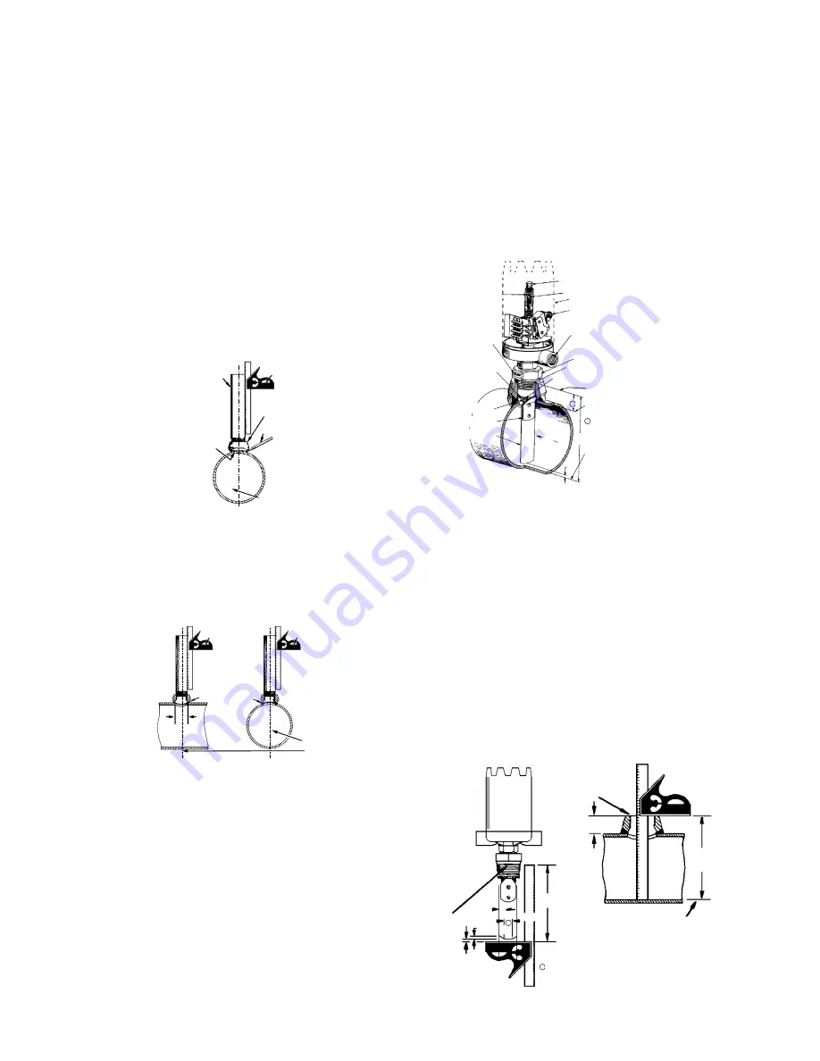
5. Proper operation of the model F10 depends upon the
vertical center line of the 2" nPT coupling being plumb
within 3°; keep fitting plumb while welding the continuous
passes according to threadolet manufacturers installation
procedure.
B. Positioning vane perpendicular to flow
6. With large and small vanes unassembled, tighten thread
the F10 body bushing into the coupling on the pipeline
until one of the 3 decal flow arrows is pointing parallel
with flow.
7. Mark the bushing thread even with the top of the
threadolet as a reference point for trimming vane to correct
length. Remove 2 arrows not parallel with pipe.
8. Remove F10 from pipeline.
9. Check position of arrow stamped on vane support
bracket. This arrow should be pointing parallel with the
flow arrow on the body bushing (as shown in
Figure 4
).
If arrows are not parallel, remove the three vane sup-
port bracket mounting screws and rotate bracket until
the stamped arrow is pointing parallel with the flow
arrow; replace mounting screws.
Figure 4
C. Trimming vane to fit line size
10. The Model F10 is furnished as standard with vanes
suitable for use on 2" through 30" pipelines. Assemble
vane (or vanes) to F10 and trim according to applicable
line size as follows:
2.00" line
(SCH.40) – Use small vane only (no cutting
should be necessary).
2.50" line
– Use small vane with large vane trimmed to
38 mm (1.50") wide (same as small vane) and length
trimmed to dimension C less 5 mm (0.19"), as shown in
Figure 5
.
3.00" line and larger
– Use small vane with large vane
length trimmed to dimension C less 5 mm (0.19"), as
shown in
Figure 5
. Upon final assembly of trimmed
vanes, firmly tighten 2 screws (item 27, page 7). It is
recommended that the lower retaining screw be peened
over on the threaded end.
Reference
mark
(note B8 &
D11)
13
(0.50)
*
19 (0.75)
*
Dimension C
6
(0.25)
5 (0.19)
(5) min.
Top of
threadolet
40 (1.56)
Dim. C
Bottom of pipeline
2
INSTALLATION
2" pipe,
±305 mm (12") long
1.5 mm (0.06") ø
spacer wire to
provide root cap
Vertical centerline
must be plumb
Air bubble in
level position
(3000 lb.)
2" threadolet fitting
Marker (note A2)
Air bubble in
level position
Air bubble in
level position
Vertical centerline
must be plumb
67 ø (2.62")
Tack weld
4 places
(see note
below)
Adjusting screw
safety retainer
Stamped arrow
located on vane
support bracket
Pivot pin
Small vane
Large vane
Flow
*
40 ± 0.06 (1.56 ± 2)
*
5 (0.19)
Flow arrow must be
pointing parallel
with the line flow
1/4"NPT plug
Adjusting screw
Cover
Switch
(SPDT dry contact shown)
Body bushing
Reference mark (note B8)
Top of 2" threadolet fitting
Top of pipeline
Dimension C
Inside bottom of pipeline
Vane support bracket with 3 mounting screws
Electrical outlet
Figure 5


