


2
Pneumatic switch
Max. supply pressure
Max. liquid temperature
Bleed orifice Ø
Code (NEMA 3R encl.)
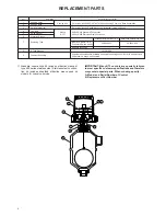
description
bar (PSIG)
°C (°F)
mm (inches)
mat'l. code 1
mat'l. code 2, 4
Series J bleed type
6.9 bar (100 PSIG)
200°C (400°F)
1.60 mm (0.063")
JDG
JDE
4.1 bar (
1
60 PSIG)
200°C (400°F)
2.39 mm (0.094")
JEG
JEE
4.1 bar (
1
60 PSIG)
230°C (450°F)
1.40 mm (0.055")
JFG
JFE
Series K non bleed type
6.9 bar (100 PSIG)
200°C (400°F)
—
—
KOE
2.8 bar (
1
40 PSIG)
200°C (400°F)
—
KOG
—
SELECT ELECTRIC SWITCH MECHANISM & ENCLOSURE
➁
All models with material of construction code 1
All models with material of construction codes 2 and 4
NEMA 4X
NEMA 7/9
BASEEFA
CENELEC
NEMA 4X
NEMA 7/9
BASEEFA
CENELEC
cast aluminium
cast iron
cast iron
cast iron
cast aluminium
cast iron
cast iron
cast iron
Switch
1"
M 20
1"
M20
3/4"
M20
3/4"
1"
M 20
1"
M20
3/4"
M20
3/4"
Description
x
PG 16
x
x
x
PG 16
x
x
NPT
1.5
NPT
1.5
NPT
1.5
NPT
NPT
1.5
NPT
1.5
NPT
1.5
NPT
Series A –
230°C
SPDT
AAP
A2P
A3P
AKR
AK8
AU8
AK7
AU7
AAQ
A2Q
A3Q
AKY
AK6
AU6
AK5
AU5
Mercury switch
(450°F)
DPDT
ADP
A8P
A9P
ANR
AN8
AX8
AD7
AW7
ADQ
A8Q
A9Q
ANY
AN6
AX6
AD5
AW5
Series B –
120°C
SPDT
BAP
B2P
B3P
BKR
BK8
BU8
BK7
BU7
BAQ
B2Q
B3Q
BKY
BK6
BU6
BK5
BU5
Snap switch
(250°F)
DPDT
BDP
B8P
B9P
BNR
BN8
BX8
BD7
BW7
BDQ
B8Q
B9Q
BNY
BN6
BX6
BD5
BW5
Series C –
230°C
SPDT
CAP
C2P
C3P
CKR
CK8
CU8
CK7
CU7
CAQ
C2Q
C3Q
CKY
CK6
CU6
CK5
CU5
Snap switch
(450°F)
DPDT
CDP
C8P
C9P
CNR
CN8
CX8
CD7
CW7
CDQ
C8Q
C9Q
CNY
CN6
CX6
CD5
CW5
Series D –
120°C
Snap switch
(250°F)
SPDT
–
–
–
–
–
–
–
–
DAQ
D2Q
D3Q
DKY
DK6
DU6
DK5
DU5
for DC
DPDT
–
–
–
–
–
–
–
–
DDQ
D8Q
D9Q
DNY
DN6
DX6
DD5
DW5
current appl.
Series E –
230°C
Vibration
(450°F)
SPDT
EAP
E2P
E3P
EKR
EK8
EU8
EK7
EU7
EAQ
E2Q
E3Q
EKY
EK6
EU6
EK5
EU5
resistant
DPDT
EDP
E8P
E9P
ENR
EN8
EX8
ED7
EW7
EDQ
E8Q
E9Q
ENY
EN6
EX6
ED5
EW5
mercury switch
Series F –
230°C
Snap switch
(450°F)
SPDT
FAP
F2P
F3P
FKR
FK8
FU8
FK7
FU7
FAQ
F2Q
F3Q
FKY
FK6
FU6
FK5
FU5
hermetically
DPDT
FDP
F8P
F9P
FNR
FN8
FX8
FD7
FW7
FDQ
F8Q
F9Q
FNY
FN6
FX6
FD5
FW5
sealed
Series HS –
230°C
Snap switch
(450°F)
SPDT
–
–
–
–
–
–
–
–
HM2
H7A
H6A
HS3
HB1
HB2
HB3
HB4
hermetically
sealed with
DPDT
–
–
–
–
–
–
–
–
HM6
H7C
H6C
HS7
HB5
HB6
HB7
HB8
terminal block
Series U –
120°C
SPDT
UAP
U2P
U3P
UKR
UK8
UU8
UK7
UU7
UAQ
U2Q
U3Q
UKY
UK6
UU6
UK5
UU5
Snap switch
(250°F)
DPDT
UDP
U8P
U9P
UNR
UN8
UX8
UD7
UW7
UDQ
U8Q
U9Q
UNY
UN6
UX6
UD5
UW5
Series W –
230°C
Snap switch
(450°F)
SPDT
WAP
W2P
W3P
WKR
WK8
WU8
WK7
WU7
WAQ
W2Q
W3Q
WKY
WK6
WU6
WK5
WU5
hermetically
DPDT
–
–
–
–
–
–
–
–
WDQ
W8Q
W9Q
WNY
WN6
WX6
WD5
WW5
sealed
Series X –
230°C
Snap switch
(450°F)
SPDT
XAP
X2P
X3P
XKR
XK8
XU8
XK7
XU7
XAQ
X2Q
X3Q
XKY
XK6
XU6
XK5
XU5
hermetically
DPDT
–
–
–
–
–
–
–
–
XDQ
X8Q
X9Q
XNY
XN6
XX6
XD5
XW5
sealed
Max.
process
temp.
°C (°F)
Cont.
one
per
encl.
MODEL IDENTIFICATION
A complete B73 switch, consists of 1 code:
MATERIALS OF CONSTRUCTION
1
Carbon steel cage with 316 SST float and 400 SST magnetic sleeve.
2
Carbon steel cage with 316 SST float, magnetic sleeve with 316 SST jacket.
4
316 SST cage and trim and float.
B 7 3
complete code for
B73 liquid float level switch
Switch mechanism and enclosure, refer to table below for pneumatic switch mechanisms and for
electric switch mechanisms.
SIZE AND TYPE OF PROCESS CONNECTION
B
2 0
1" NPT threaded connection upper side/bottom
B
3 0
1" NPT socket weld connection upper side/bottom
➁
Housing heater and drain available in option. Consult factory for proper
model numbers.
③
Max. Process temperatures are based on 38°C (100°F) ambient tem-
perature.
SELECT PNEUMATIC SWITCH MECHANISM & ENCLOSURE
1" ANSI type
NW 25 DIN FORM C
(DIN 2526)
▼
FLANGE TYPE & SIZE
150 lbs
300 lbs
ND 16
(DIN 2533)
ND 25
(DIN 2534)
▼
MOUNTING STYLE
N30
N40
1FA
1GA
flanged connection upper side/bottom
S30
S40
1FB
1GB
flanged connection side/side
③
▼