background image

IMPULSE®•G+/VG+ Series 4 24 V Power Supply Installation Manual -  November 2011
1-26

8.

 With the option unit now affixed to the bracket, reinstall the bracket back in its original location.

NOTE:

Take proper precautions when connecting the option so the option will easily fit onto the 
drive. Make sure the connector cable is not pinched between the option and the drive.

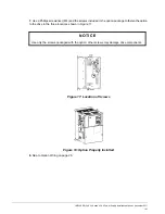
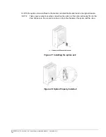
Figure 27: Installing the option unit

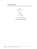
Figure 28: Option Properly Installed

Содержание PS-A10H

Страница 1: ...24 V Power Supply Installation Manual PS A10H and PS A10L November 2011 Part Number 144 23928 Copyright 2011 Magnetek...

Страница 2: ...rovided by Magnetek must be promptly provided to the end user Magnetek offers an express warranty only as to the quality of its products in conforming to standards and specifications published in the...

Страница 3: ...l injury or damage products and related equipment and systems DANGER DANGER indicates an imminently hazardous situation which if not avoided will result in death or serious injury This signal word is...

Страница 4: ...ering new copies of the manual contact a Magnetek representative and provide the manual number shown on the front cover DANGER Heed the safety messages in this manual Failure to comply may result in d...

Страница 5: ...shown in the Figure 1 Follow all warnings and safety instructions when using the product When using the drive in an area that may require displaying warning information in Japanese and English a warni...

Страница 6: ...provide power to the main circuit of the drive It is possible to read fault and parameter data in the drive via the operator or network communications when the drive switches to the option as a back...

Страница 7: ...odel or the option does not function properly Option Package Contents 1 The warning label packaged with the option must be affixed to the option to maintain UL listing Refer to Option Label Warnings o...

Страница 8: ...G Series 4 24 V Power Supply Installation Manual November 2011 1 8 4 Option Components 24 V Power Supply Option Figure 2 24 VDC Power Supply Option Components Option Nameplate Figure 3 PS A10L Namepla...

Страница 9: ...Power Supply Installation Manual November 2011 1 9 Terminal Block TB1 Refer to Table 2 for details on TB1 terminal functions Terminal Functions Table 2 Option Terminal Functions Terminal Function 24 2...

Страница 10: ...n this section may include options and drives without covers or safety shields to show details Be sure to reinstall covers or shields before operating any devices Use the option according to the instr...

Страница 11: ...ment Failure to comply may cause further damage to the equipment Do not connect or operate any equipment with visible damage or missing parts Do not use unshielded cable for control wiring Failure to...

Страница 12: ...l packaged with the drive for information on wiring and connecting the drive Single Drive Installation Figure 4 shows the installation distance required to maintain sufficient space for airflow and wi...

Страница 13: ...ion should be placed within the enclosure This product must be used in areas with an environment rating no greater than pollution degree 2 according to UL standards NOTE 575 V class drives models 5XXX...

Страница 14: ...to 2075 4001 to 4039 5001 to 5027 A 1 14 2085 to 2415 4045 to 4370 5032 to 5200 B 1 18 4450 to 4605 C 1 22 DANGER Electric Shock Hazard Disconnect all power to the drive and wait at least the amount...

Страница 15: ...amount of time for voltage to dissipate then remove the connector cover by pushing on the connector tab and sliding the cover towards the top of the drive as indicated by the arrow in Figure 6 Figure...

Страница 16: ...the option with the insertion tabs on the drive as shown in Figure 9 Figure 9 Align the Option and the Drive NOTE Take proper precautions when connecting the option so the option will easily fit onto...

Страница 17: ...24 V Power Supply Installation Manual November 2011 1 17 5 Slide the option downward as indicated in Figure 10 to lock it into place on the drive Figure 10 Slide the Option onto the Drive 6 Skip to Op...

Страница 18: ...12 Figure 12 Slide the Connector Cover DANGER Electric Shock Hazard Disconnect all power to the drive and wait at least the amount of time specified on the drive front cover safety label After all ind...

Страница 19: ...f a straight edge screwdriver into the opening shown in Figure 13 Pull the connector cover in the direction indicated by the arrow and remove it from the drive Figure 13 Remove the Connector Cover 4 P...

Страница 20: ...bs on the option with the insertion tabs on the drive as shown in Figure 16 NOTE Take proper precautions when connecting the option so the option will easily fit onto the drive Make sure the connector...

Страница 21: ...d the screws included in the option package to fasten the option to the drive in the three locations shown in Figure 17 Figure 17 Location of Screws Figure 18 Option Properly Installed 8 Skip to Optio...

Страница 22: ...d Disconnect all power to the drive and wait at least the amount of time specified on the drive front cover safety label After all indicators are off measure the DC bus voltage to confirm safe level a...

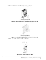
Страница 23: ...move the bracket used to hold the 24 V power supply unit in place Figure 20 Removing the bracket 4450 G VG S4 4605 G VG S4 Figure 21 Removing the bracket 4810 G VG S4 41090 G VG S4 3 Pull the loose en...

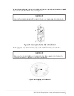
Страница 24: ...n in Figure 23 the cable and connector should pass through the bracket Figure 23 Pass the cable and connector through the bracket 5 Connect the option unit to the bracket so that the connector tabs on...

Страница 25: ...re 25 Figure 25 Securing the Option Unit to the Bracket 7 Firmly plug the end of the connection cable into the CN19 connection port on the drive Figure 26 Plugging the connector NOTICE Use only the sc...

Страница 26: ...the bracket reinstall the bracket back in its original location NOTE Take proper precautions when connecting the option so the option will easily fit onto the drive Make sure the connector cable is n...

Страница 27: ...24 V Power Supply Installation Manual November 2011 1 27 9 Skip to Option Wiring on page 28 After wiring the terminal TB1 reinstall the drive covers to their original locations Figure 29 Reinstall th...

Страница 28: ...tighten the terminal screws to hold wiring in place Refer to Wire Gauges and Tightening Torques on page 29 to confirm that the proper tightening torque is applied to each terminal Take particular prec...

Страница 29: ...auges mm2 Recomm Gauges mm2 24 0 FE M2 0 22 to 0 2 1 95 to 2 21 Standard wire 0 25 to 1 0 24 to 17 AWG Single line 0 25 to 1 5 24 to 16 AWG 0 75 18 AWG 0 25 to 0 5 24 to 20 AWG 0 5 20 AWG Shielded cab...

Страница 30: ...Uninstalling the Option There are three different Uninstallation methods for the option based on drive model Find the drive model number on the drive nameplate and refer to Table 6 to determine the pr...

Страница 31: ...e the option in the direction indicated by the arrow Figure 32 Uninstallation Method A Uninstallation Method B Remove the three screws used to fasten the option into place during installation as shown...

Страница 32: ...Series 4 24 V Power Supply Installation Manual November 2011 1 32 Uninstallation Method C After removing the drive covers remove the bracket and option unit as shown in Figure 34 Figure 34 Uninstallat...

Страница 33: ...ion indicating proper option operation 4 The digital operator on the drive will display Uv for about 10 seconds to indicate an undervoltage condition on the drive If Uv does not flash on the display s...

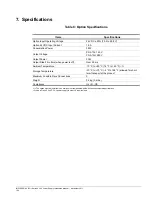
Страница 34: ...0L 140 V PS A10H 280 V Output Power 30 W Output Ride Thru time when power is off Over 50 ms Ambient Temperature 10 C to 60 C 14 F to 140 F 1 Storage Temperature 20 C to 70 C 4 F to 158 F allowed for s...

Отзывы: