


Section 6 – Installation Diagrams (Continued)
Telemotive Laser Guard Instruction Manual – October 2009
29
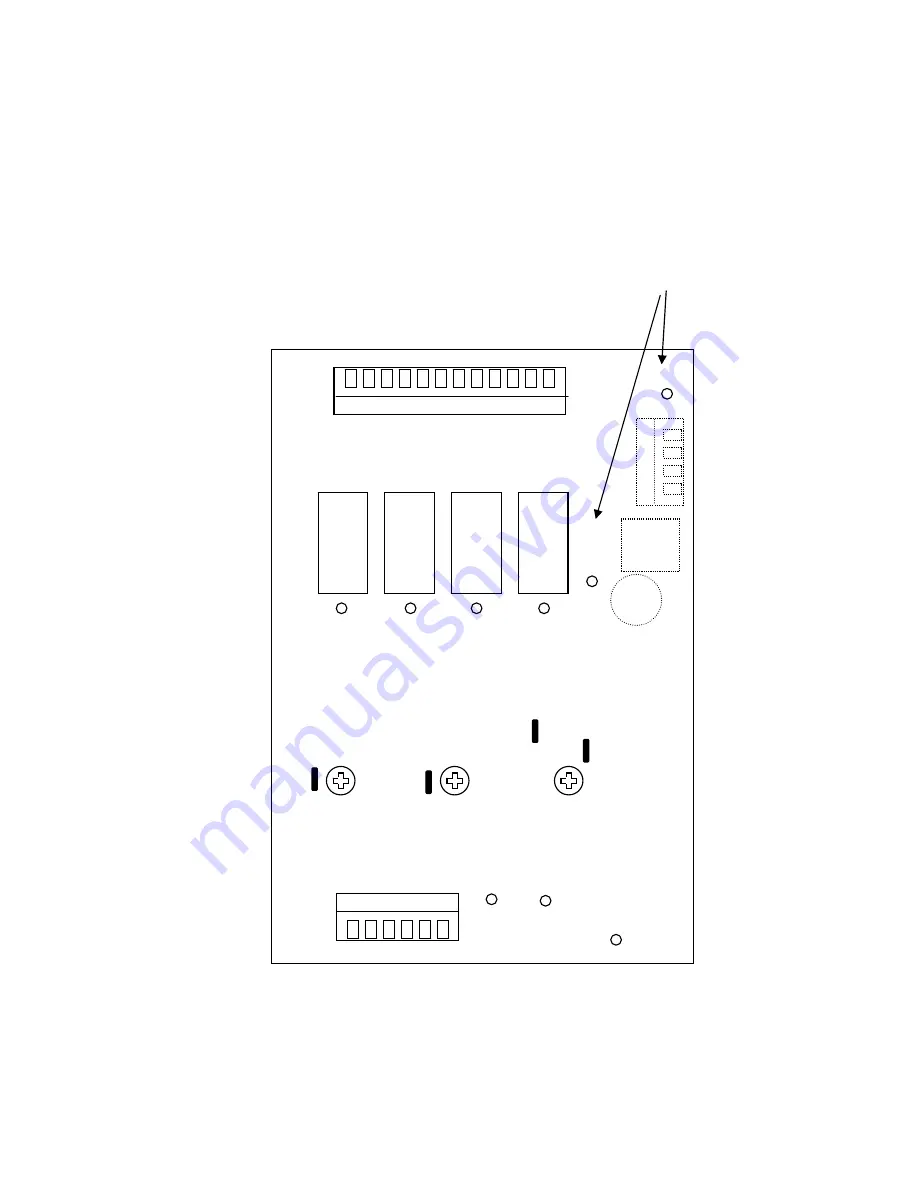
Figure 6-13. Test Point Locations
DS7
DS5
DS6
DS1
DS2
DS3
DS4
DS8
DS9
OPTICAL
PATH
FAULT
2
ND
SEQ.
3
rd
SEQ.
RELAY 1
RELAY 2
RELAY 3
RELAY 4
TP 1 1
ST
RANGE
TEST POINT
TP2 2
ND
RANGE
TEST POINT
TP3 3
RD
RANGE
TEST POINT
Onl
y
on E14008
GND


