background image

E

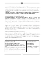
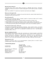
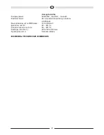
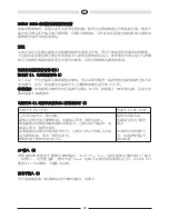
• No utilice productos de limpieza o disolventes químicos durante la limpieza. Ello podría dañar la

superficie del dispositivo.

Las reparaciones tienen que ser hechas siempre por técnicos especializados, ya que el usuario corre

el peligro de exponerse a altos voltajes o a otros tipos de riesgos.

LOS SUBWOOFER ACTIVOS DE LA SERIE MAGNAT OMEGA

Al conectar su instalación de altavoces asegúrese de que todos los aparatos están desconectados.

Asimismo, compruebe que todos los cables de los altavoces están colocados con la polaridad correcta,

es decir, que el polo positivo de la salida correspondiente está conectado al polo positivo de la entrada

correspondiente y que el polo negativo esté conectado con su polo negativo correspondiente. Siga las

instrucciones de manejo de su receptor/amplificador y las de los altavoces.

COLOCACION

El campo de frecuencia que da el subwoofer no es localizable por el oído humano, por lo que la

colocación no suele resultar problemática. No obstante, es preferible colocarlo delante del lugar de

audición, cerca del altavoz frontal.Asimismo, se recomienda que la distancia lateral y la trasera de objetos

y paredes sea de al menos 20 cm, ya que en caso contrario la reproducción de sonidos bajos puede verse

afectada.

LOS ELEMENTOS DE MANEJO DEL SUBWOOFER (FIGURA 1)

CONEXIÓN A LA RED (1), SELECTOR DE TENSIÓN DE RED (2)

Dado que se trata de un subwoofer con amplificador incorporado, éste debe conectarse a la línea de

alimentación a través del cable adjunto. El selector de tensión de red ha sido ajustado desde la fábrica

a 230 V para su empleo en el ámbito europeo.

Muy importante

: Si el subwoofer se conecta en la posición 115 V a la red de 230 V, ¡esto destruirá

forzosamente el amplificador incorporado!

INTERRUPTOR POWER (3), INDICADOR LED DEL ESTADO DE FUNCIONAMIENTO (4)

ENTRADAS AV (5)

Conecte la salida de bajo nivel del subwoofer de su receptor (Sub-Pre-Out) con la entrada AV del

subwoofer (véase la ilustración 3). Para ello necesitará un cable mono cinch (no está incluido en el

material suministrado).

Por medio del conector hembra LINK OUT (11) es posible conectar otro subwoofer.

Interruptor Power ON

Interruptor Power OFF

El encendido / apagado automático es activado.

Si el subwoofer recibe una señal del receptor, se enciende

automáticamente, y el diodo luminoso se ilumina en verde.

Si el subwoofer ya no recibe ninguna señal, tras unos pocos minutos

pasará automáticamente al modo standby, y el diodo luminoso se

ilumina en rojo.

Consumo de energía en estado de standby: 0,5 vatio

Subwoofer apagado

Diodo luminoso apagado.

Si el aparato no va a

utilizarse durante un largo

espacio de tiempo, se

recomienda que se

seleccione este modo.

E

E

20

Содержание OMEGA SUB 20A

Страница 1: ...OMEGA SUB 20A OMEGA SUB 25A BEDIENUNGSANLEITUNG GARANTIEURKUNDE OWNER S MANUAL WARRANTY DOCUMENT MODE D EMPLOI CERTIFICAT DE GARANTIE...

Страница 2: ...Verf gung stehenden R ckgabe und Sammelsystemen zu At the end of the product s useful life please dispose of it at appropriate collection points provided in your country Une fois le produit en fin de...

Страница 3: ...4 D 7 GB 10 F 13 NL 16 I 19 E 22 25 S 28 RUS 32 CHN 35 J 38 Abbildungen Illustrations P...

Страница 4: ...s darf der Subwoofer nicht zumAbstellen von Vasen oder anderen mit Fl ssigkeiten gef llten Beh ltern verwendet werden Der Abstand zwischen Aktivsubwoofergeh use und Zimmerw nden oder anderen Gegenst n...

Страница 5: ...htigt werden kann DIE BEDIENUNGSELEMENTE DES SUBWOOFERS BILD 1 Netzanschluss 1 Netzspannungswahlschalter 2 Da es sich um einen Subwoofer mit eingebautem Verst rker handelt muss dieser ber das beiliege...

Страница 6: ...zum Einsatz ist eine Einstellung von 50 Hz 100 Hz sinnvoll Phasenschalter 9 Im Normalfall sollte der Phasenschalter auf 0 eingestellt werden In seltenen F llen kann es jedoch von Vorteil sein die Pha...

Страница 7: ...recipients on top of the subwoofer The distance between the active subwoofer enclosure and the walls of the room or other objects e g furniture shelf units may not be less than 5 cm on any side The a...

Страница 8: ...d walls is at least 20 centimetres as otherwise bass reproduction may be impaired THE SUBWOOFER S OPERATING ELEMENTS FIG 1 Mains connection 1 mains voltage switch 2 The subwoofer is equipped with an i...

Страница 9: ...100 Hz when used with stand loudspeakers Phase switch 9 In normal use the phase switch should be set to 0 However in rare cases it may be advantageous to set the phase to 180 e g if the subwoofer is...

Страница 10: ...posez jamais des vases ou d autres r cipients contenant des liquides sur le subwoofer La distance entre le bo tier du subwoofer actif et les murs de la pi ce ou les autres objets par ex meubles parois...

Страница 11: ...re afin que la reproduction sonore de la basse ne soit pas alt r e COMPOSITION DU SUBWOOFER FIG 1 Branchement au secteur 1 selecteur de tension 2 Le subwoofer est muni d un amplificateur int gr qui do...

Страница 12: ...aut parleurs colonne un r glage entre 50 Hz et 100 Hz est alors ing nieux Interrupteur de phase 9 Normalement l interrupteur de phase doit tre plac sur 0 Dans des cas assez rares il peut parfois tre a...

Страница 13: ...de subwoofer De afstand tussen de behuizing van de actieve subwoofer enerzijds en de wanden van de ruimte of eventuele andere objecten zoals meubels of kasten anderzijds mag aan alle kanten niet mind...

Страница 14: ...n naar achteren toe tenminste 20 cm bedraagt Hierdoor voorkomt u dat de basweergave negatief wordt be nvloed DE BEDIENELEMENTEN VAN DE SUBWOOFER AFB 1 Netaansluiting 1 Spanningsschakelaar 2 Het betref...

Страница 15: ...n te stellen op 50 Hz 100 Hz Faseschakelaar 9 Over het algemeen moet de faseschakelaar worden ingesteld op AV 0 In een enkele uitzondering kan het echter van voordeel zijn de fase in te stellen op 180...

Страница 16: ...ggiati vasi o altri contenitori contenenti liquidi La distanza tra l alloggiamento del subwoofer attivo e le pareti della stanza o altri oggetti ad es mobili pareti attrezzate non deve essere inferior...

Страница 17: ...compromessa la riproduzione dei bassi GLI ELEMENTI DI CONTROLLO DEL SUBWOOFER FIGURA 1 COLLEGAMENTO ALLA RETE 1 INTERRUTTORE DI SELEZIONE TENSIONE DI RETE 2 Essendo un subwoofer con amplificatore inte...

Страница 18: ...50 Hz 100 Hz L INTERRUTORE DI FASE 9 Nel funzionamento normale si consiglia di posizionare l interruttore di fase su 0 In pochi casi potrebbe essere vantaggioso impostare la fase su 180 ad es In caso...

Страница 19: ...de l quido No exponer nunca el subwoofer a salpicaduras y chorros de agua El subwoofer tampoco debe utilizarse para colocar floreros u otros recipientes llenados de l quido La distancia entre la caja...

Страница 20: ...ede verse afectada LOS ELEMENTOS DE MANEJO DEL SUBWOOFER FIGURA 1 CONEXI N A LA RED 1 SELECTOR DE TENSI N DE RED 2 Dado que se trata de un subwoofer con amplificador incorporado ste debe conectarse a...

Страница 21: ...Hz INTERRUPTOR DE FASES 9 Normalmente el interruptor de fases deber estar en la posici n AV 0 No obstante en unos pocos casos podr resultar beneficioso el colocar la fase a 180 p ej en los casos en lo...

Страница 22: ...cheios de l quido A dist ncia entre todos os lados da caixa do subwoofer activo e as paredes ou outros objectos por exemplo m veis e estantes n o deve ser menor que 5 cm A placa de alum nio ou as ale...

Страница 23: ...NDO DO SUBWOOFER FIGURA 1 Liga o rede el ctrica 1 selector da tens o da rede 2 Por tratar se aqui de um subwoofer com amplificador integrado preciso lig lo atrav s do cabo fornecido rede el ctrica O s...

Страница 24: ...de fase deveria ser ajustado em 0 Em alguns casos por m pode ser vantajoso ajustar a fase em 180 por exemplo no caso de dist ncia grande entre o subwoofer e os altifalantes frontais ou em caso de prop...

Страница 25: ...ker plats Uts tt aldrig subwoofern f r dropp och st nkvatten och st ll aldrig vaser eller andra v tskebeh llare p subwoofern Avst ndet mellan den aktiva subwooferns k pa och rummets v ggar eller andra...

Страница 26: ...yssnarplatsen i n rheten av fronth gtalarna Dessutom b r du se till att avst ndet till f rem l sidov ggar och bakv ggen uppg r till minst 20 cm f r att f rhindra att bas tergivningen d mpas SUBWOOFERN...

Страница 27: ...t llning mellan 50 Hz 100 Hz rekommenderas FASOMKOPPLARE 9 I normalfall ska fasomkopplaren st p 0 I vissa fall kan det vara l mpligt om fasen st r p 180 t ex vid l ngt avst nd mellan subwoofern och fr...

Страница 28: ...RUS MAGNAT 5 5 bass reflex 10 C 40 C RUS RUS 28...

Страница 29: ...RUS MAGNAT OMEGA 20 20 1 1 2 230 115 230 3 4 ON OFF 0 5 RUS RUS 29...

Страница 30: ...RUS AV 5 Sub Pre Out AV 3 Mono Cinch LINK OUT 11 6 2 7 1 2 3 4 8 100 150 50 100 9 0 180 10 TE Omega Sub 20A bassreflex downfire 21 RMS 100 200 24 200 50 200 x x 250 x 450 x 430 RUS RUS 30...

Страница 31: ...Omega Sub 25A bassreflex downfire 26 RMS 140 280 22 200 50 200 x x 300 x 500 x 460 RUS RUS 31...

Страница 32: ...CHN M M A A G G N N A A T T 5 cm 5 cm 10 C 40 C CHN CHN 32...

Страница 33: ...CHN M MA AG GN NA AT T O OM ME EG GA A 20 1 1 1 1 2 2 230 115 230 3 3 4 4 A AV V 5 5 Su b P re O u t A V 3 C i nch LI N K O U T 11 6 6 2 O N O FF 0 5 CHN CHN CHN 33...

Страница 34: ...50 100 9 9 0 180 1 10 0 O Om me eg ga a S Su ub b 2 20 0A A O Om me eg ga a S Su ub b 2 25 5A A dow nfi re dow nfi re 21 26 RM S M ax 100 200 140 280 24 200 22 200 50 200 50 200 x x 250 x 450 x 430 3...

Страница 35: ...J M MA AG GN NA AT T 5 cm 5 cm 10 C 40 C J J 35...

Страница 36: ...J J M MA AG GN NA AT T O OM ME EG GA A 20 cm 20 cm 1 1 1 1 2 2 230 V 115 V 230 V 3 3 L LE ED D 4 4 A AV V 5 5 Sub Pre Out AV 3 LINK OUT 11 6 6 2 ON OFF LED LED 0 5 OFF LED OFF J J J 36...

Страница 37: ...z 50 Hz 100 Hz 9 9 0 180 1 10 0 O Om me eg ga a S Su ub b 2 20 0A A O Om me eg ga a S Su ub b 2 25 5A A 21 cm 26 cm RMS Max 100 200 Watt 140 280 Watt 24 200 Hz 22 200 Hz 50 200 Hz 50 200 Hz 250 x 450...

Страница 38: ...1 38...

Страница 39: ...39...

Страница 40: ...40...

Страница 41: ...luded The guarantee period is not altered by the fact that we have carried out guarantee work 3 Unauthorized tampering with the equipment will invalidate this guarantee 4 Consult your authorized deale...

Страница 42: ...rial No Name und Anschrift des H ndlers Stempel Name and address of the dealer stamp K ufer Customer Name Name Stra e Street PLZ Ort City Land Country Nur g ltig in Verbindung mit Ihrer Kaufquittung N...

Страница 43: ......

Страница 44: ...Magnat Audio Produkte GmbH Lise Meitner Str 9 D 50259 Pulheim Germany Tel 49 0 2234 807 0 Fax 49 0 2234 807 399 Internet http www magnat de...

Отзывы: