background image

       1-800-MAGLINE (624-5463) 


 Page 58                                               www.magliner.com

CooLift

®

Area

Description

Method of  Inspection

Normal Condition

Findings 

Pass or Fail

Timing

Notes

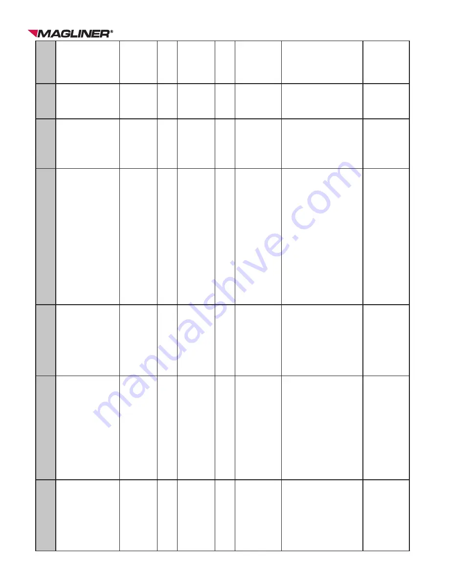
Brake System

Mounting screws tight • Master cylinder mount to  handle • Master cylinder cap • Connecting block to base of  enclosure • Caliper mounting

Manual inspection

• 

Parts are tight to mounting surfaces

W

eekly

Brake System

Mounting screws on brake  discs are tight

Visual inspection

• 

Mounting screws on brake disc are  not backing out

• 

Brake disc is mounted tightly to the  center wheel

W

eekly

Hydraulics

Cylinders not leaking (note  especially front cylinder)

Visual inspection

Thin film of oil on piston rod

W

eekly

Hydraulics

Cylinder condition • No rod scoring • Return springs fully  functional

Visual inspection

Cylinder rod is smooth and retracts  fully into cylinder body

W

eekly

Suspension

Wheels and tires are in good  condition

Visual inspection

Wheels and tires are free of damage

W

eekly

Suspension

Components are straight and  undamaged • Front wheel mounting yoke • Main axle • Rear swivel caster frames

Manual inspection

• 

Components are not damaged and  operate freely

• 

Main axle plating is not cracked or  damaged

W

eekly

Operator Interface

External mounting screws  are tight • Base plate mounting to  frame • Enclosure mounting or base  plate • Handle mounting screws • Switch mounting hardware  is tight

Manual inspection

Components are tight to mounting  surfaces

W

eekly

Operator Interface

• 

Handle, enclosure and door  are free of damage and in  good condition

• 

Door latches are fully  functional

Visual inspection

• 

Straight sections

• 

Smooth curves

• 

Flat surfaces

• 

Minor scratches and dings are  expected

W

eekly

Содержание CooLift CPA43

Страница 1: ...gliner com CooLift Serial ________________________________ Date of Purchase ________________________ Service Manual IMPORTANT Read entire manual before operating For CooLift models with electric hydra...

Страница 2: ...rger 18 Replacing Charger Cord 19 20 Replacing Power Switches 21 Replacing Directional Switch 21 Replacing Battery Meter 22 Replacing Circuit Breaker 23 Replacing Propulsion Controller 24 Electrical S...

Страница 3: ...our vise grip plier clamps size 6r Channel locks Rubber mallet Drift pin 1 2 socket w extension and ratchet Needle nose pliers 1 flat head screwdriver 4mm 5mm Allen wrench 5 16 9 64 Allen wrench Tape...

Страница 4: ...R 7 16 WRENCH 7 64 ALLEN WRENCH NOTE Replacing a handle on the CooLift requires that the entire handle assembly first must be removed See Vertical Loop Handle Removal for instructions 1 Turn off main...

Страница 5: ...interlock button and cable 1 309667 B Vertical loop handle LH 1 309568 C Horizontal brace 1 309560 D Pan head machine screw 1 4 20 x 1 1 2 long 6 80105 E Hex lock nut 1 4 20 10 80675 F Pan head machin...

Страница 6: ...he connector Remove throttle cable 6 Put new throttle on by pushing the cable into the new throttle until the plastic lock clicks 7 Put two screws back into the top of the throttle with the lever towa...

Страница 7: ...evel flooring surface with the holding brake engaged 2 Turn off main power switch Remove back panel Disconnect the batteries 3 Unplug throttle interlock button wiring harness from the main wiring harn...

Страница 8: ...ft will be used in the 53 pallet configuration a new saddle plate 309151 will need to be installed 7 Lift and remove the saddle plate Then lift and remove the bulk head frame to disengage from the bas...

Страница 9: ...e plate for CTA43 1 309341 C Containment strap 1 1 309152 D Containment strap mounting spacer 1 1 309150 E Screw 3 8 16 x 1 1 2 long 1 1 79988 F Hex lock nut 3 8 16 1 1 80603 G Screw 1 4 20 x 2 3 4 lo...

Страница 10: ...plate 309151 will need to be installed 7 Lift and remove the saddle plate Then lift and remove the bulk head frame to disengage from the base plate CPA48 BULK HEAD INSTALLATION TOOLS NEEDED 7 16 WRENC...

Страница 11: ...A Bulk head for CTA48 1 309791 B Bulk head saddle plate for CTA48 1 309341 C Containment strap 1 1 309152 D Containment strap mounting spacer 1 1 309150 E Screw 3 8 16 x 1 1 2 long 1 1 79988 F Hex loc...

Страница 12: ...ng 2 80012 B Pallet stop CPA43 models 1 309826 Pallet stop CPA48 models 1 309206 C Hex lock nut 5 16 18 2 80676 Quantities listed are for both sides of the CooLift CTA48 CTA43 REPLACING CORNER POST TO...

Страница 13: ...tion Remove and replace only one caster at a time 1 With the cart sitting on a level flooring surface the holding brake engaged and the rear access panel removed remove the battery ies 2 Loosen the th...

Страница 14: ...rt the flat head screwdriver into end of the slotted frame that holds the brush section and bend the end of the slot open enough to allow the old sections to slide out A B 6 Remove the old brush secti...

Страница 15: ...k 1 309825 B Flat head machine screw 1 4 20 x 2 long 4 80224 C Hex lock nut 1 4 20 4 80675 D Slotted truss head screw 3 8 16 x 1 2 long 2 80286 REPLACING BACK PANEL LATCH TOOLS NEEDED 3 PHILLIPS SCREW...

Страница 16: ...can be placed safely on sturdy surfaces that raise the CooLift at least 12 off the ground 2 Remove the front and rear pans using the T30 Torx screwdriver 3 Remove the center brace using 1 2 wrench 4 W...

Страница 17: ...nut H allowing the tongue to rotate freely REPLACING CONTAINMENT STRAP TOOLS NEEDED TWO 1 2 WRENCHES Note It is important to keep the CooLift upright at all times 1 Place the CooLift on a level floori...

Страница 18: ...ure 3 Plug the input cord in the new charger 9 Center the charger in the mounting bracket NOTE The charger ON OFF switch should be oriented towards the back wall 10 Carefully place the charger and mou...

Страница 19: ...then strip each wire back 9 16 from the end ii Insert the cord end through the cord plug base then insert and secure the three wires to the plug terminals a Green wire to center terminal b Black or b...

Страница 20: ...long with C13 connector on one end 1 64020 D Plug 15A rated 5 15p three prong cord plug 1 61053 Figure 2 A Wiring Part Diagram Jam nut Cord grip A Figure 1 Hex lock nut B D C REWORK PURCHASED CORD TO...

Страница 21: ...itch and connect them to the new replacement switch making sure to follow the same connection layout 4 When all of the new connections have been made the damaged switch should be able to be removed by...

Страница 22: ...end does not fall back through the hole of the enclosure 7 Disconnect the white wire from the KEYSWITCH terminal of the battery meter and ensure the wire end does not fall back through the hole of the...

Страница 23: ...4 When all of the new connections have been made the damaged circuit breaker should be able to be removed by grasping it firmly in one hand and removing the hex nut on the outside of the enclosure she...

Страница 24: ...p is at the bottom 10 Plug in the clutch connector 11 Plug in the motor connectors Please read below it may be different from what s expected a The motor wire labeled connects to the M tab b The motor...

Страница 25: ...1 800 MAGLINE 624 5463 Page 25 www magliner com CooLift FULL ELECTRICAL SCHEMATIC 63019 63019 BRKR BRKR...

Страница 26: ...ad cap screws B and insert through the adjustment plate and into the CooLift onto the LH side rail finger tighten only for now 13 Apply blue thread locker to the two 2 long hex head cap screws C Inser...

Страница 27: ...plate toward front of motor Remove these screws from new motor Item Qty Part Number A Socket head cap screw 5 16 18 x 3 long 2 80126 B Hex head cap screw 5 16 18 x 1 long 4 80011 C Hex head cap screw...

Страница 28: ...justment plates on the outside of the CooLift frame secure to the lock nuts in the clutch bearing plate with four screws washers and lock nuts Do this for both sides Finger tighten only for now 14 Rot...

Страница 29: ...1 81071 D Clutch bearing mount plate RH 1 309835 E Clutch bearing mount plate LH 1 309836 F Clutch assembly 1 309676 Clutch adjustment plate A F B C E D Clutch arm Tape can be used to keep lock nuts i...

Страница 30: ...e rail lip Once plates are removed the differential can drop from the CooLift frame 15 Retain the differential mount assemblies and reinforcement plates 16 Remove the 4 1 4 long screws H hex lock nuts...

Страница 31: ...on the motor adjustment plates until the chain has 1 4 of play between the two sprockets Make sure that the motor adjustment plates are the same distance apart from the differential mount block see p...

Страница 32: ...he up switch until fully extended 4 Position a spacer block between the deck and the base of the cart 5 Turn off main power switch 6 Remove the brake caliper D by removing the caliper mounting screws...

Страница 33: ...D orientation to the brake disc C Then the screws may be tightened using the 5mm Allen wrench 17 Bleed the brake system see Bleeding the Brakes Quantities listed are for one side of the CooLift Compr...

Страница 34: ...til fully extended 4 Position a spacer block between the deck and the base of the cart 5 Turn off the main power switch 6 Remove the brake caliper C by removing the caliper mounting screws A using a 5...

Страница 35: ...lbs 16 Position the caliper C within the caliper mount and lightly hand tighten the mounting screws A Figure 4 NOTE Do not use the wrench on them until the caliper has been aligned or damage to the br...

Страница 36: ...ush washers F using the 12mm wrench Drain as much brake fluid as possible into the drip pan NOTE Do not engage the brake lever while the brake line is removed 6 Remove the brake line D from the master...

Страница 37: ...B C D F G E F G H H Item Qty Part Number A Master cylinder 1 309218 B Cord grip PG 21 1 309124 C Hex lock nut PG 21 1 309125 D Master cylinder brake line 1 309083 E Junction block 1 309051 F Copper wa...

Страница 38: ...lock between the deck and the base of the cart 4 Turn off main power switch 5 Remove the battery see Replacing Battery Box 6 Position the drip pan below the caliper A and remove the banjo bolt D using...

Страница 39: ...firmly pull towards the inside of the deck to remove the clip 5 Align a new brake clip so that the point of the brake clip will enter the frame from the inside of the unit and push the clip to snap i...

Страница 40: ...ile the reservoir cover is off because it may introduce air into the system 4 Position the new master cylinder A in place on the horizontal grip and tighten into place using the T30 wrench 5 Take the...

Страница 41: ...1 309218 B Cover screws n a C Reservoir cover n a D Copper washer 2 80712 E Banjo bolt 1 80124 F Master cylinder brake line includes G 1 309083 G Banjo fitting n a G B C Quantities listed are for qua...

Страница 42: ...of the master cylinder A to keep fluid from splashing out but do not tighten the screws 9 Pump the brake handle eight to ten times and note the amount of pressure it takes each time If the amount of p...

Страница 43: ...and refill the reservoir if necessary after every other cycle 16 Repeat the previous three steps on the right side caliper of the cart then repeat these same steps for the left side caliper Keep repea...

Страница 44: ...nd drain as much of the hydraulic fluid as possible into the drip pan 6 Remove the three screws F that hold the pump mount plate C to the vertical slides using the 3 Phillips head screwdriver NOTE Tak...

Страница 45: ...enoid to terminal block 1 64035 C Pump mount plate 1 309831 D Pump assembly includes items all pictured in Figure 3 1 63013 E Flat head machine screw 5 16 18 x 3 4 long 3 80261 F Pan head machine scre...

Страница 46: ...ooden spacer blocks on edge 5 Lower the cylinders completely using the electric pump 6 Turn off the power switch 7 Remove the bottom front and rear pans 8 Loosen the hydraulic fittings from each hydra...

Страница 47: ...NE CYLINDER WAS REPLACED Items Qty Part Number A Line tee to front cylinder 1 55420 B Line tee to rear cylinder 1 55421 C Line tee to coupling 1 55422 D Tee fitting 1 55403 E Cylinder assembly include...

Страница 48: ...t number and rev level on the cylinder body above the port 1 Place the CooLift on a level flooring surface with the holding brake engaged 2 Turn off main power switch 3 Remove the back access panel fr...

Страница 49: ...ish tightening both of the bleed screws to 40 in lbs torque for all cylinders 16 Check for leaks in the hydraulic system 17 Clean the excess fluid out of the deck screw tapped hole 18 Secure the deck...

Страница 50: ...k of the spring as it will be used within the new assembly 3 Place the spring inside the new pawl B as illustrated in Figure 3 and slide it in place over the end of the brake lever and secure with the...

Страница 51: ...ure it is working properly A RELOCATING MASTER CYLINDER TOOLS NEEDED TORX T30 WRENCH Note It is important to keep the CooLift upright at all times 1 Place the CooLift on a level flooring surface 2 Loo...

Страница 52: ...oLift on 4x4 blocks on a level flooring surface 2 Turn off main power switch 3 Engage the parking brake and remove the wheel retaining lock nut with the 1 1 8 wrench Remove the flat washer 4 Disengage...

Страница 53: ...pump is running but the deck is not lifting Is the fluid level correct in the reservoir Do you see any leaks in the hydraulic system Is the manual pump release valve open Is the breather cap for the p...

Страница 54: ...the CooLift deck Check for leaks in the brake system and tighten loose components or repair any damaged components Wipe up any fluid that may have leaked into the drip pan using shop towels Contact Ma...

Страница 55: ...osition Remove cover protecting the propulsion system Turn off CooLift Oil chains lightly with a 40 weight or greater oil Moly chain lubricant may be used as a substitute Lift deck to its fully raised...

Страница 56: ...No squeaks or groans from cylinders Manual bypass valve should not leak Method of Inspection Visual inspection Visual inspection Push cart and let roll Roll cart at walking speed and apply brakes Loc...

Страница 57: ...eekly Frame Frame is in good condition No damage No excessive wear Visual inspection Straight sections Smooth curves Flat surfaces Minor scratches and dings are expected Weekly Frame Containment strap...

Страница 58: ...fully functional Visual inspection Cylinder rod is smooth and retracts fully into cylinder body Weekly Suspension Wheels and tires are in good condition Visual inspection Wheels and tires are free of...

Страница 59: ...h Manual inspection No loose components Wiring harness are not damaged Check connectivity Monthly Brake System Fluid level Visual inspection Fluid level up to notch in master cylinder reservoir Monthl...

Страница 60: ...der body Monthly Hydraulics Fluid level Visual inspection Fluid should be about 1 2 inch below top of reservoir when deck is down Monthly Suspension Wheels and casters spin freely Manual inspection Wh...
Страница 61: ...inks Minimal play between pins and bushings Bushings are not working out of links Manual Visual inspection Links are straight with no signs of damage or wear Minimal play between pins and links Bushin...

Страница 62: ...ps connectors and solder joints Manual inspection No loose connections crimps or solder joints Quarterly Electrical Control boards Manual Visual inspection No loose components Wiring harness connector...

Страница 63: ...1 800 MAGLINE 624 5463 Page 63 www magliner com CooLift...

Страница 64: ...om CooLift MAGLINE INC Standish Michigan 48658 1 800 MAGLINE 624 5463 www magliner com Form B9364 REV November 2019 Copyright 2015 2019 Magline Inc Patent www magliner com patents CooLift is a registe...

Отзывы: