ES
FR
EN
IT
22
Madas Technical Manual
- 9|9.4 - REV. 0 of 8
th
Feb 2019
MTC10
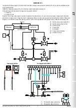
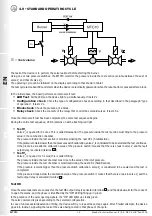
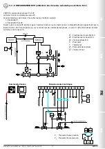
EXAMPLE 3
V1: NC safety solenoid valve
V2: NC work solenoid valve
V3: Pilot valve
P: Pressure switch
T: Thermostat
LP: Minimum pressure switch
: Test volume
P
1
: Low pressure switch
P
2
: High pressure switch
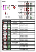
Valve Control
Electrical connections
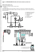
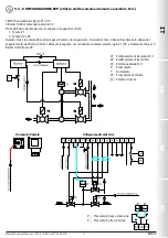
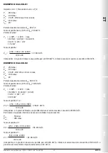
In the following diagram the leak test is carried out by using an auxiliary valve V3 that can also be used as a pilot valve.
The MTC10 controls valves V1 and V3. The Burner Control controls valve V2.
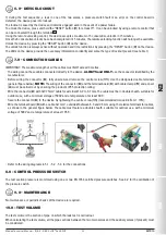
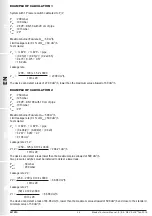
The following checks are performed before starting the burner:
1. Leak test V1
2. Leak test V2 and V3
During the test, the gas can be discharged into the combustion chamber or, if this is not allowed, it must be released outside
in a safe place. After the test, the device waits for the signal provided by the Burner Control. Once the signal is received, V1
and V3 on the valve control connector are opened (in line with the signal provided). The Burner Control opens V2.


