


13
Madas Technical Manual
- 3|3.2aJ - REV. 0 of 1
st
Aug 2019
M16/RMJ N.A. - MBA/RMJ N.A.
IT
EN
FR
ES
1
2
3
4
5
6
7
8
9
10
piping
application
discharge in open air
internal thermal unit
external roof
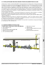
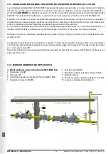
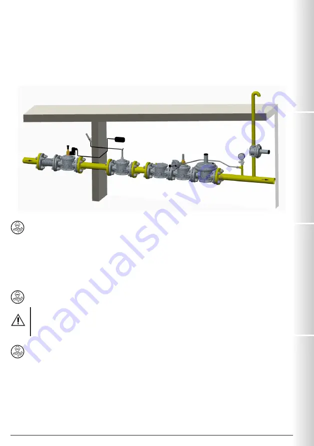
3.4 - GENERIC EXAMPLE OF AN INSTALLATION
1. M16/RMJ N.A. Manual reset solenoid valve
2. SM jerk ON/OFF valve
3. FM gas filter
4. OPSO series MVB/1 MAX shut off valve
5. RG/2MC pressure regulator
6. MVS/1 relief valve
7. Pressure gauge and relative button
8. Gas detector
9. SM remote jerk ON/OFF valve lever control
10. Compensation/Vibration damping joint
4.0 - MANUAL RESET
To reset the solenoid valve:
• Make sure the valve is
NOT
electrically powered;
• Close the flow downstream of the solenoid valve in order to balance the pressure between upstream and downstream when
opening;
• Pull the reset knob (
17
) slightly and wait a few seconds for the pressure upstream and downstream of the valve to stabilise;
• After balancing the pressures, pull the reset knob (
17
) until it connects.
NOTE
: the green band (
15
), when visible, indicates that the valve obturator is open.
5.0 - FIRST START-UP
• Before start-up make sure that all of the instructions on the rating plate, including the direction of flow, are observed;
• After gradually pressurising the plant, check tightness and operation of the solenoid valve by supplying/cutting
off the electricity.
IMPORTANT NOTE
: Do not use the connector as a switch to open / close the solenoid valve.
• Make sure the solenoid valve is closed by electrically connecting it.
5.1 - RECOMMENDED PERIODIC CHECKS
• Use a suitable calibration tool to ensure the bolts are tightened as indicated in 3.2;
• Check tightness of the flanged/threaded connections on the system;
• Check tightness and operation of the solenoid valve;
• Clean the product regularly to prevent dust from building up;
• It is essential to eliminate the risk of ignition caused by stray currents or any condition of potential difference between the
devices fitted on the system. Periodically check that there is good electrical conduction between the valve body and the
equipotential plant line and between the coil and the equipotential plant line.
It is the responsibility of the final user or installer to define the frequency of these checks based on the severity of the service
conditions.


