background image

18

IT

EN

FR

ES

• Cut out power prior to proceeding with wiring;
• According to the plant geometry, check the risk of explosive mixture arising inside the piping;
• If the solenoid valve is installed near other devices or as part of an assembly, compatibility between the solenoid 

valve and this other device must be evaluated beforehand.

•Avoid installing the solenoid valve near surfaces that could be damaged by the coil temperature;
•Provide a protection against impacts or accidental contacts if the solenoid valve is accessible to unqualified 

personnel.

  3.2 - INSTALLATION 

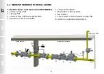
(see example in 3.4) 

Threaded devices: 

• Assemble the device by screwing it, with the due seals, onto the plant with pipes and/or fittings with the right threading for 

the connection being attached. 

• Do not use the coil (

4

) as a lever to help you screw it on, only use the specific tool; 

• The arrow, shown on the body (

9

) of the device, needs to be pointing towards the application;

Flanged devices: 

• Assemble the device by flanging it, with the due seals, onto the plant with pipes whose flanges are consistent with the 

connection being attached. The gaskets must be free from defects and must be centred between the flanges;

• If, after installing the gaskets, there is still an excessive space in between, do not try to reduce the said gap by excessively 

tightening the bolts of the device; 

• The arrow, shown on the body (

9

) of the device, needs to be pointing towards the application;

• Insert the relative washers inside the bolts in order to prevent damage to the flanges during tightening;

Содержание M16/RM N.A.

Страница 1: ...0 DN 50 P max 0 5 bar ELETTROVALVOLA A RIARMO MANUALE NORM APERTA PER GAS NORMALLY OPEN MANUAL RESET SOLENOID VALVE FOR GAS LECTROVANNE A R ARMEMENT MANUEL NORMALEMENT OUVERTE POUR GAZ ELECTROV LVULA...

Страница 2: ...e os 47 Dimensioni tabella 1 Dimensions table 1 Dimensions tableau 1 Dimensiones tabla 1 52 Bobine e connettori di ricambio tabella 2a 2b 53 Spare coils and connectors table 2a 2b Bobines et connecteu...

Страница 3: ...DESCRIZIONE Elettrovalvole di intercettazione per gas a riarmo manuale normalmente aperte idonee all intercettazione del gas per segnalazioni di pericolo inviate da rivelatori presenza gas metano gpl...

Страница 4: ...cadere la garanzia del prodotto potrebbe compromettere il corretto funzionamento dello stesso Il fabbricante non responsabile di malfunzionamenti derivanti da manomissioni non autorizzate o utilizzo d...

Страница 5: ...ne IP65 Resistenza meccanica Gruppo 2 secondo EN 13611 Attacchi filettati Rp DN 20 DN 25 DN 32 DN 40 DN 50 secondo EN 10226 Attacchi flangiati accoppiabili con flange PN 16 DN 25 DN 32 DN 40 DN 50 ISO...

Страница 6: ...sforzi meccanici calcolare inoltre lo spazio per l inserimento della guarnizione di tenuta Per le fasi di serraggio necessario munirsi di una o pi chiavi dinamometriche tarate od altri utensili di bl...

Страница 7: ...o 3 2 INSTALLAZIONE vedere esempio in 3 4 Apparecchi filettati Assemblare il dispositivo avvitandolo assieme alle opportune tenute sull impianto con tubi e o raccordi le cui filettature siano coerenti...

Страница 8: ...nto Non pu essere posizionato capovolto con la manopola di riarmo 17 rivolta verso il basso Durante l installazione evitare che detriti o residui metallici penetrino all interno dell apparecchio Garan...

Страница 9: ...cavo da utilizzare deve essere in doppia guaina idoneo per uso esterno con tensione minima 500V e temperatura di almeno 60 C Collegare all alimentazione i morsetti 1 e 2 e il cavo di terra al morsetto...

Страница 10: ...DI INSTALLAZIONE 1 Elettrovalvola ariarmomanualeM16 RMN A 2 Valvola a strappo SM 3 Filtro gas FM 4 Valvola di blocco OPSO serie MVB 1 MAX 5 Regolatore di pressione RG 2MC 6 Valvola di sfioro MVS 1 7 M...

Страница 11: ...te le indicazioni presenti in targhetta inclusa la direzione del flusso siano rispettate Dopo aver pressurizzato in maniera graduale l impianto verificare la tenuta e il funzionamento dell elettrovalv...

Страница 12: ...della bobina 4 e rimuoverla dal cannotto 1 assieme alle apposite guarnizioni dischetti Inserire nel cannotto 1 la nuova bobina guarnizioni dischetti e fissare il tutto tramite l apposita vite Aggancia...

Страница 13: ...9 0 DATI DI TARGA In targa vedere esempi a fianco sono riportati i seguenti dati Nome logo e indirizzo del fabbricante eventuale nome logo distributore Mod nome modello dell apparecchio seguito dal d...

Страница 14: ...e numbers provided on the last page 1 1 DESCRIPTION Normally open manual reset solenoid valves for gas suitable to shut off gas and signal danger sent by gas detectors methane LPG carbon monoxide and...

Страница 15: ...arranty it could compromise correct device operation The manufacturer is not liable for malfunctions caused by unauthorised tampering or use of non original parts 1 5 IMPROPER USE The product must onl...

Страница 16: ...p 2 according to EN 13611 Rp threaded connections DN 20 DN 25 DN 32 DN 40 DN 50 according to EN 10226 Flanged connections to be coupled with PN 16 flanges DN 25 DN 32 DN 40 DN 50 ISO 7005 EN 1092 1 NP...

Страница 17: ...late the space to insert the seal gasket With regard to tightening operations equip yourself with one or two calibrated torque wrenches or other controlled locking tools The safety regulations on hand...

Страница 18: ...plant with pipes and or fittings with the right threading for the connection being attached Do not use the coil 4 as a lever to help you screw it on only use the specific tool The arrow shown on the...

Страница 19: ...be put in upside down with the reset knob 17 pointing downwards During installation avoid debris or metal residues from getting into the device To guarantee mechanical tension free assembly we recomm...

Страница 20: ...use with a minimum voltage of 500V and a temperature of at least 60 C Connect terminals 1 and 2 to the power supply and the earth cable to terminal Secure the connector 3 to the coil 4 tightening rec...

Страница 21: ...MPLE OF AN INSTALLATION 1 M16 RM N A Manual reset solenoid valve 2 SM jerk ON OFF valve 3 FM gas filter 4 OPSO series MVB 1 MAX shut off valve 5 RG 2MC pressure regulator 6 MVS 1 relief valve 7 Pressu...

Страница 22: ...ions on the rating plate including the direction of flow are observed After having gradually pressurized the system check the seal and operation of the solenoid valve electrically powering disconnecti...

Страница 23: ...armature assembly 1 along with the gaskets discs Place the new coil gaskets discs inside the armature assembly 1 and secure with the relative screw Couple the connector to the coil and secure it as i...

Страница 24: ...9 0 RATING PLATE DATA The plate data see examples provided here includes the following Manufacturer s name logo and address possible distributor name logo Mod name model of the device followed by the...

Страница 25: ...a derni re page 1 1 DESCRIPTION lectrovannes d interception du gaz r armement manuel normalement ouvertes adapt es l interception du gaz pour signalisations de danger envoy es par des d tecteurs de pr...

Страница 26: ...arantie du produit mais risque galement de compromettre le bon fonctionnement de ce dernier Le fabricant n est pas responsable des dysfonctionnements dus des manipulations non autoris es ou l utilisat...

Страница 27: ...e 2 conform ment la norme EN 13611 Raccords filet s Rp DN 20 DN 25 DN 32 DN 40 DN 50 en conformit avec la norme EN 10226 Raccords brides coupler avec des brides PN 16 DN 25 DN 32 DN 40 DN 50 ISO 7005...

Страница 28: ...forts m caniques inutiles calculer en outre l espace pour l insertion du joint d tanch it Pour les phases de serrage se munir d une ou de plusieurs cl s dynamom triques calibr es ou autres outils de v...

Страница 29: ...4 Appareils filet s Assembler le dispositif en le vissant avec ses joints opportuns sur l installation avec les tuyaux et ou raccords dont les filetages doivent tre coh rents avec la connexion assembl...

Страница 30: ...positionn renvers avec le bouton rotatif de r armement 17 tourn vers le bas Pendant l installation viter que des d chets ou des r sidus m talliques ne p n trent l int rieur de l appareil Garantir un m...

Страница 31: ...le utiliser doit tre doublement gain adapt une utilisation ext rieure avec une tension minimale de 500 V et une temp rature d au moins 60 C Raccorder les bornes 1 et 2 l alimentation et le c ble de te...

Страница 32: ...s rie MVB 1 MAX 5 R gulateur de pression RG 2MC 6 Vanne anti d bordement MVS 1 7 Manom tre et son bouton 8 D tecteur de gaz 9 Levier de commande distance de la vanne d chirement SM 10 Joint de compens...

Страница 33: ...ications pr sentes sur la plaque y compris le sens du flux soient respect es Apr s avoir pressuris progressivement l installation v rifier l tanch it et le fonctionnement de l lectrovanne en mettant s...

Страница 34: ...elesjoints disquessp cifiques Ins rer dans la douille 1 la nouvelle bobine les joints les disques et fixer le tout avec la vis appropri e Accrocher le connecteur la bobine et le fixer comme indiqu au...

Страница 35: ...urelle 9 0 DONN ES NOMINALES Sur la plaque signal tique voir l exemple ci contre sont report es les donn es suivantes Nom logo et adresse du Fabricant ventuellement nom logo du revendeur Mod nom mod l...

Страница 36: ...ma p gina 1 1 DESCRIPCI N Electrov lvulas de corte para gas con rearme manual normalmente abiertas adecuadas para interceptar el gas ya sea por avisos de peligro enviados por detectores de presencia d...

Страница 37: ...dem s de invalidar la garant a del producto podr a perjudicar su correcto funcionamiento El fabricante se exime de toda responsabilidad por problemas de funcionamiento que se deriven de alteraciones n...

Страница 38: ...5 Resistencia mec nica Grupo 2 seg n EN 13611 Conexiones roscadas Rp DN 20 DN 25 DN 32 DN 40 DN 50 seg n EN 10226 Conexiones embridadas acoplables con bridas PN 16 DN 25 DN 32 DN 40 DN 50 ISO 7005 EN...

Страница 39: ...de estanqueidad Para las fases de apriete es necesario procurarse una o varias llaves dinamom tricas calibradas u otras herramientas de bloqueo controladas Deben respetarse las normativas de seguridad...

Страница 40: ...dolo junto con las juntas correspondientes en la instalaci n con tuber as y o racores cuyos roscados encajen con la conexi n a acoplar No use la bobina 4 como palanca para atornillar use la herramient...

Страница 41: ...ocar volcado con el bot n de rearme 17 dirigido hacia abajo Durante la instalaci n evite que la suciedad o residuos met licos penetren dentro del aparato Garantice un montaje sin tensiones se recomien...

Страница 42: ...8 1 mm El cable debe contar con doble funda id neo para usos exteriores con una tensi n m nimo de 500 V y temperatura m nima de 60 C Conecte a la alimentaci n los bornes 1 y 2 y el cable de tierra al...

Страница 43: ...CI N 1 Electrov lvulaconrearmemanualM16 RMN A 2 V lvula de corte SM 3 Filtro gas FM 4 V lvula de seguridad por m xima OPSO serie MVB 1 MAX 5 Regulador de presi n RG 2MC 6 V lvula de alivio MVS 1 7 Man...

Страница 44: ...ebe que se respeten todas las indicaciones presentes en la placa incluida la direcci n del flujo Tras haber presurizado de forma gradual la instalaci n compruebe la estanquidad y el funcionamiento de...

Страница 45: ...DEL CONECTOR Desenrosque completamente y quite el tornillo central 2 y desenganche el conector 3 de la bobina 4 Despu sdehaberquitadoelcableadoel ctricointeriorexistente cableeelnuevoconectoryf jelota...

Страница 46: ...formaci n de condensaci n El producto al final de su vida til deber eliminarse por separado respecto a los dem s residuos Directiva RAEE 2012 19 UE y en conformidad con la legislaci n vigente en el pa...

Страница 47: ...uncionamiento del producto IP Grado de protecci n 230 V Tensi n de alimentaci n frecuencia si es V CA seguidas por el consumo el ctrico TS Intervalo de temperatura en el que se garantiza el funcionami...

Страница 48: ...48 IT EN FR ES fig 1 Rp DN 20 Rp DN 25 fig 2 Rp DN 32 Rp DN 40 Rp DN 50...

Страница 49: ...49 IT EN FR ES fig 3 DN 32 FL DN 40 FL DN 50 FL...

Страница 50: ...i di fissaggio coperchio 13 Molla di chiusura 14 Perno centrale 15 Fascetta verde VPI 16 O Ring di tenuta perno 17 Manopola di riarmo fig 1 2 and 3 1 Coil armature assembly 2 Connector clamping screw...

Страница 51: ...4 Perno central 15 Abrazadera verde VPI 16 Junta t rica de estanquidad perno 17 Bot n de rearme FR fig 1 2 et 3 1 Fourreau de la bobine 2 Vis de fixation du connecteur 3 Connecteur lectrique 4 Bobine...

Страница 52: ...accords brides Conexiones bridadas fori holes trous orificios A B C D E DN 20 DN 25 120 152 94 29 5 122 5 DN 32 DN 40 160 198 140 37 161 DN 50 160 218 140 45 173 PN 16 ANSI 150 DN 25 4 191 180 115 57...

Страница 53: ...dice connettore Connector code Code du connecteur C digo del conector Potenza assorbita Absorbed power Puissance absorb e Potencia absorbida DN 20 DN 50 12 Vdc BO 0010 BO 0010 12 V DC CN 0010 20 VA 12...

Страница 54: ...V DC 2 W CN 0010 2 VA Tipo connettore Connector type Type de connecteur Tipo de conector CN 0010 Normale Normal Normal Normal Attenzione combinazioni indicate in tabelle 2a e 2b valide solo per valvo...

Страница 55: ...P1 50 mbar Tabla de p rdidas de carga calculado con P1 50 mbar dv densit relativa all aria dv density relative to the air dv densit relative l air dv densidad relativa del aire 1 metano methane m tha...

Страница 56: ...us nous r servons le droit de toute modification technique et constructive Nos reservamos el derecho de realizar cualquier cambio t cnico y estructural Sede legale Via V Moratello 5 6 7 37045 Z A I Le...

Отзывы: