background image

14 

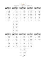
Voltages 

Using the EHX 24v supply measuring -34.68 / no load 

4558

DC

NE570

DC

4558

DC

4558

DC

4558

DC

1

-7.48

1

-13.74

1

-6.41

1

-7.48

1

-7.48

2

-7.48

2

-12.98

2

-3.21

2

-7.48

2

-7.48

3

-7.44

3

-12.99

3

-3.18

3

-7.44

3

-7.46

4

-14.82

4

-14.82

4

-14.82

4

-14.82

4

-14.82

5

-7.40

5

-13.00

5

-7.46

5

-7.43

5

-6.69

6

-7.48

6

-12.97

6

-7.48

6

-7.45

6

-6.76

7

-7.48

7

-4.71

7

-7.48

7

-7.45

7

-6.76

8

0.00

8

-12.99

8

0.00

8

0.00

8

0.00

9

-12.99

10

-6.76

11

-8.48

12

-12.99

13

0.00

14

-12.99

15

-12.99

16

-13.76

BBD

DC

BBD

DC

CD4047

DC

4558

DC

LM7915

DC

1

0.00

1

0.00

1

-7.94

1

vaires

I

-25.57

2

-7.48

2

-7.49

2

-7.09

2

-7.14

G

0.00

3

-10.12

3

-9.71

3

-6.91

3

vaires

O

-15.00

4

-10.12

4

-9.70

4

0.00

4

-15.00

5

-14.99

5

-15.00

5

0.00

5

-7.14

6

-7.49

6

-7.49

6

0.00

6

-7.14

7

-7.66

7

-7.45

7

-15.00

7

vaires

8

-14.05

8

-14.06

8

-15.00

8

0.00

9

-15.00

10

-7.49

11

-7.48

12

-15.00

13

-7.01

14

0.00

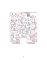
IC5

IC6

IC7

IC8

IC9

REG

IC1

IC2

IC3

IC4

Содержание Total Recall

Страница 1: ...anpedals 3 34 W x 3 875 H Terms of Use You are free to use purchased Total Recall circuit boards for both DIY and small commercial operations You may not offer Total Recall boards for resale or as part of a kit in a commercial fashion Peer to peer re sale is of course okay ...

Страница 2: ...2 ...

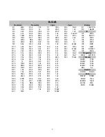
Страница 3: ... R13 51k R44 100k C13 33n C44 10uF R14 16k R45 6k8 C14 1uF C45 10uF REG LM7915 R15 33k R46 39k C15 220n C46 100uF R16 33k R47 15k C16 2n7 GAIN1 100k R17 1k R48 3k3 C17 2n7 GAIN2 100k R18 100k R49 13k C18 4u7 BIAS1 100k R19 680k R50 910k C19 47n BIAS2 100k R20 100k R51 910k C20 2n7 BAL 5k R21 16k R52 120k C21 2n7 R22 16k R53 7k5 C22 4u7 CH VB On On R23 33k2 R54 27k C23 1uF R24 24k3 R55 27k C24 1uF ...

Страница 4: ...arbon Film 1 4W 2u2 1 Electrolytic 25v Min 24k3 1 Metal Carbon Film 1 4W 2u2 1 Non Polar 25v Min 27k 2 Metal Carbon Film 1 4W 4u7 3 Electrolytic 25v Min 33k 2 Metal Carbon Film 1 4W 10uF 4 Electrolytic 25v Min 33k2 1 Metal Carbon Film 1 4W 47uF 1 Electrolytic 25v Min 39k 2 Metal Carbon Film 1 4W 100uF 1 Electrolytic 25v Min 47k 1 Metal Carbon Film 1 4W 470uF 1 Electrolytic 35v 51k 1 Metal Carbon F...

Страница 5: ...5 ...

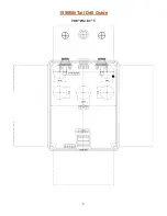
Страница 6: ...6 1590BB Tall Drill Guide 7 08 W x 8 1 T ...

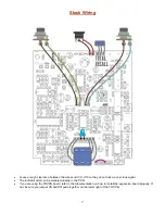
Страница 7: ... do not pick up any clock signal The indicator LED can be soldered directly to the PCB If you are using the TRXPN board refer to that documentation on how to install the expansion board properly If not be sure you jumper XS and XR pads together on the lower right of the TR PCB ...

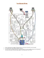
Страница 8: ...hey do not pick up any clock signal The indicator LED can be soldered directly to the PCB If you are using the TRXPN board refer to that documentation on how to install the expansion board properly If not be sure you jumper XS and XR pads together on the lower right of the TR PCB ...

Страница 9: ...w amazon com Electro Harmonix US24DC 100 24V Power Supply dp B0042RHT4M You should be able to use an 18v supply instead of the 24v one listed above although this has not been tested You will need to do a couple things 1 Lower the value of R57 from 240R 1W to something like 22R 1W and 2 make sure you know what the polarity of your 18v power supply is before hooking it up to the TR PCB It s expensiv...

Страница 10: ...ck before wiring it to the PCB and use your multi meter to verify which lug on the jack is negative DC Once you have verified polarity on the jack hook up the PCB to the power supply Now check the LM7915 regulator to verify that you are getting about 15v output Once that is complete disconnect the power and start loading in the ICs EHX power supply wiring for positive ground The clearance in the f...

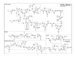
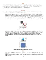
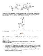
Страница 11: ...s of the chip pins 3 and 4 The output is the delayed signal where the delay time is controlled by the two out of phase clock signals pins 2 and 6 generated by the CD4047 and processed through the sequential bucket steps The two outputs are mixed together and then sent to a gain recovery stage This helps make up any volume loss introduced by the sequential steps in the BBD 2048 steps for MN3008 and...

Страница 12: ...ull up FDBK a little less than halfway up MOD all the way down LEVEL about 1 3rd up BLEND doesn t matter you should leave the circuit output disconnected since we will be audio probing CH VB switch doesn t matter Leave all the trimmers in their halfway position to start Connect the TR PCB to your power supply Use an audio source at the input of the circuit J1 While you can just strum your guitar i...

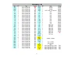
Страница 13: ... until the output is the same or slightly above the volume input of pin7 on IC6 You are done If you are using the BBD expansion board refer to that documentation on how to do this procedure with four BBDs It is generally the same thing with a few added steps Mouser Cart For convenience I have created a cart in Mouser that includes most of the items in the BOM All the items highlighted in blue are ...

Страница 14: ...48 7 4 71 7 7 48 7 7 45 7 6 76 8 0 00 8 12 99 8 0 00 8 0 00 8 0 00 9 12 99 10 6 76 11 8 48 12 12 99 13 0 00 14 12 99 15 12 99 16 13 76 BBD DC BBD DC CD4047 DC 4558 DC LM7915 DC 1 0 00 1 0 00 1 7 94 1 vaires I 25 57 2 7 48 2 7 49 2 7 09 2 7 14 G 0 00 3 10 12 3 9 71 3 6 91 3 vaires O 15 00 4 10 12 4 9 70 4 0 00 4 15 00 5 14 99 5 15 00 5 0 00 5 7 14 6 7 49 6 7 49 6 0 00 6 7 14 7 7 66 7 7 45 7 15 00 7...

Страница 15: ...15 ...

Отзывы: