


Change the position of the springs.
With this product, the positions of the built-in
anti-vibration springs must be changed according
to the angle of installation. The product will not
provide the regular resistance to vibration if the
anti-vibration springs are not in the correct
positions or if the left and right springs are in
different positions.
The anti-vibration springs can be placed at ”H”
or ”V” angle.
The springs are set to the”H” angle upon
shipment from the factory. To change this angle,
follow the instructions given below.
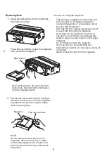
1. Change the position
of the springs using
a finger.
2. Stick on the left and
right side surface
cover labels.
Be sure to apply the
cover labels after
setting the position
of the springs so as
to protect the interior
of the product from dust or dirt which may cause
malfunction.
3. Check the position of the springs. Make a final
check of the position of the springs using the
five small holes in the left and right side surface
cover labels.
H
0
90
V
0
90
H
V
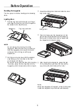
Remove the shipping keys.
Three keys are mounted to the changer’s bottom
panel to protect the product during shipment. Be
sure to remove these keys before installing the
unit. So as not to lost the keys, store them and
cover the key holes with the included dust-
prevention seals.
NOTES
The eject operation cannot be performed if
the keys are mounted when the power is
turned on. Turn the power off, then remove
the keys.
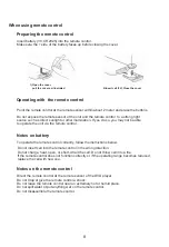
Install the L-shaped bracket.
1 Determine the position and angle installation.
2 Referring to step , change the position of
the springs according to the angle of
installation.
3 Install the L-shaped bracket according to
the angle of installation. Fasten it in place
using the Hex bolts(M5x6)
Example of installation using attached
L-shaped bracket.
Vertical
Horizontal
19
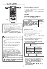
NOTES
To prevent external noise from entering the
audio system.
Don’t connect the ground of the changer
to the car chassis.
Please connect the changer to the vehicle
with the L-shaped bracket,
hex bolts, adhesive tape
and insulating pad like the
figure shows.
Peel off the adhesive tapes
and press the tape onto the
bottom of L-shaped bracket.
Содержание M-DVDG1CH
Страница 1: ...E nglish ALDINET S P A VIALE C COLOMBO 8 20090 TREZZANO S N MI ITALY 6 DISC DVD CHANGER...
Страница 2: ......
Страница 3: ......
Страница 4: ......
Страница 5: ......
Страница 6: ......
Страница 9: ......
Страница 11: ......
Страница 12: ......
Страница 13: ......
Страница 14: ......
Страница 15: ......
Страница 16: ......
Страница 17: ......
Страница 18: ......
Страница 19: ......
Страница 20: ......
Страница 23: ......
Страница 24: ......


