background image

24 

Configuration and Operation


© 2020 MacroAir Technologies     Toll Free: 866 668 3247     Fax: 909 890 2313      www.macroairfans.com   

Controller 30 Operation Manual 90-30016-00 Rev A-01 Date: 031920 

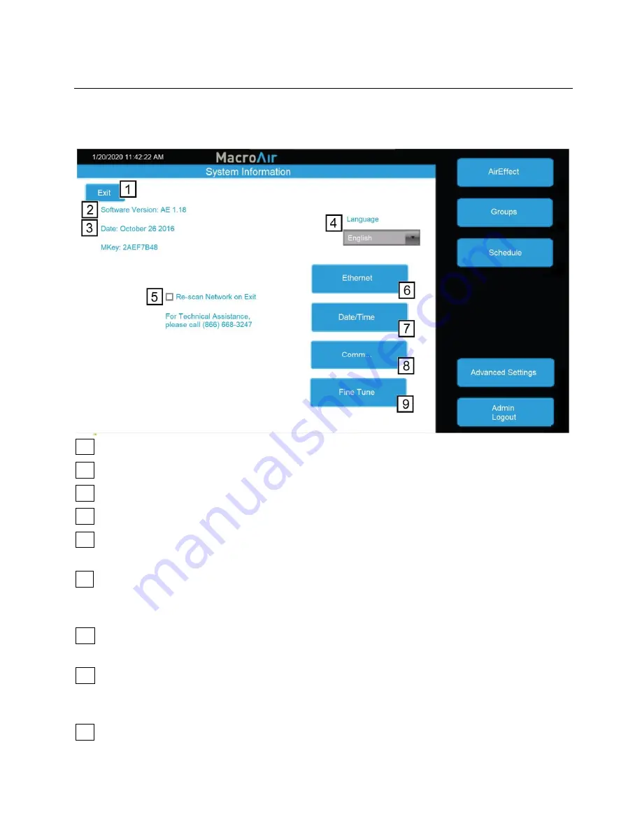
Advanced Settings Screen 

Tapping on the 

“Advanced Sett

ings

” button will bring you to

 the Advanced Settings screen. This 

screen  is  very  similar  to  the  Settings  screen,  but  contains  4  additional  advanced  options 
(Ethernet, Date/Time, Comm and Fine Tune). 

  1    

Home

 -  Goes back to the Home screen. 


  2    

Software Version

 -  Indicates the software version of the touch screen. 


  3    

Date

 -  Displays the revision date of the screen software. 


  4    

Language

 -  Allows selection of alternate languages. 


  5    

Re-scan Network on Exit

 - When selected, rescans the network to detect any changes. Used 

after adding/removing fans or changing addresses. 


  6   

Ethernet

  -  This  page  displays  the  Ethernet  information  for  the  screen.  This  information  is 

used  to  remotely  control  the  screen  with  a  program  such  as  VNC  viewer.  More  information  is 
available in the Remote Operation section of the manual (pg 28). 


  7   

Date/Time

  -  This  screen  allows  you  to  set  the  date/time.  This  is  very  important  for 

scheduling, as the screen will run schedules according to the programmed date/time. 


  8   

Comm

  -  This  screen  provides  access  to  the  Modbus  communications  page.  This  is  a 

password-protected page and is only accessible with MacroAir technical support on the phone. 
If you need access to this page, please call us at (866) 668-3247. 


  9   

Fine  Tune

  -  This  screen  allows  you  to  adjust  the  maximum  speed  of  each  fan.  More 

information on the Fine Tune page (pg 27). 
 

Содержание Controller 30

Страница 1: ...Operation Manual Controller 30 ...

Страница 2: ......

Страница 3: ...s Fan Placement and Spacing Fan Network Ordering 5 Controller Dimensions 6 Controller Components 7 Network Wiring Requirements 8 Network Wiring Configurations 9 Network Excess Cable 10 Controller Wiring Instructions 11 AVD 370 RJ45 Wiring Instructions 12 T Splice Connection Method for ADV 370 Fans 14 Fan Wiring Instructions 16 Mixed Network Wiring Instructions 17 AirEffect Sensor 18 Controller Set...

Страница 4: ...se of not complying with the recommendations outlined in the manual Electrical Guidelines WARNING Electrical Damage Improper electrical installation can cause damage to the fan and interfere with other electronic equipment In addition to standard electrical safety considerations please observe the following MacroAir Cables The wiring from the control panel to the fan MUST be MacroAir supplied shie...

Страница 5: ...Electrical Code requirements with respect to grounding of all equipment WARNING Do Not Touch Many of the parts of this unit operate at line voltage DO NOT TOUCH WARNING Covers Install all covers before applying power or starting and stopping the unit Installation and Service WARNING Damage Do not operate or install any fans or fan accessories that appear to be damaged WARNING Death and Injury Fail...

Страница 6: ... the fans Mounting Guidelines WARNING Weight Considerations We recommend that a building structure be capable of holding approximately twice the stated hanging weight of the fan If there is some doubt of this a professional contractor or architect should perform a thorough evaluation of the building prior to purchasing the fans MacroAir provides guidelines for mounting fans however it is the sole ...

Страница 7: ...s best at 20 to 30 feet above the floor but acceptable performance has been demonstrated as low as 10 feet and as high as 50 feet WARNING Mezzanine Placement If the building has a mezzanine fans should be mounted so a person cannot reach a fan in any way from the upper level deck Make certain that fans are positioned so that blade tips are at least three 3 feet away from any area where a person ma...

Страница 8: ...6 Introduction 2020 MacroAir Technologies Toll Free 866 668 3247 Fax 909 890 2313 www macroairfans com Controller 30 Operation Manual 90 30016 00 Rev A 01 Date 031920 Controller Dimensions ...

Страница 9: ...anual 90 30016 00 Rev A 01 Date 031920 Controller Components Note The glands for the fire alarm and CAT5e to local network are plugged from the factory in order to maintain the screen s IP 66 rating when not used If you are utilizing the fire alarm option and or remote operation remove the plugs from any gland you will be using ...

Страница 10: ... voltage AC cables Do not exceed 4000ft 1219m of CAT5e between the screen and the last fan in the network A repeater is required for every five 5 AVD 370 fans Repeaters need to be evenly placed throughout the network which will not necessarily be at every 5th fan Refer to the below wiring diagrams for further information Daisy Chain Network MacroAir fans must be connected in one single line referr...

Страница 11: ...l Free 866 668 3247 Fax 909 890 2313 www macroairfans com Controller 30 Operation Manual 90 30016 00 Rev A 01 Date 031920 Network Wiring Configurations Improper Wiring Configuration End of Line x3 End of Line x8 Proper Wiring Configuration ONE End of Line ...

Страница 12: ...noise being emitted throughout a typical industrial commercial environment extra cable should not be coiled up as the coil itself will create noise interference in the communication signal There should be no more than 2ft 0 6m of excess cable at each connection point If more than 2ft 0 6m of cable is needed for future relocation of the fan run the cable up toward the ceiling and back down in a hor...

Страница 13: ...of the network controller and wire the blue and blue white wires to the touchscreen per the diagram below Do not remove any factory wiring 4 5 If a fire alarm is being used a normally closed relay can be tied into the orange and orange white wire coming from the fans If a fire alarm is not being used the orange pair needs to be twisted together 6 If you are utilizing the optional remote operation ...

Страница 14: ...fans com Controller 30 Operation Manual 90 30016 00 Rev A 01 Date 031920 AVD 370 RJ45 Wiring Instructions AVD 370 fans with RJ45 ports on the board are wired in T splices Each T splice will consist of 3 CAT5e cables A properly wired T splice network is shown below Typical T Splice of CAT5e Network Cable ...

Страница 15: ...oairfans com Controller 30 Operation Manual 90 30016 00 Rev A 01 Date 031920 AVD 370 RJ45 Wiring Instructions cont A repeater is required for every 5 fans which will be spliced evenly in the CAT5e network between fans Repeaters are not required on networks with 4 fans or less Repeater Wiring Diagram ...

Страница 16: ... than 2ft 0 6m on each CAT5e to strip the wires and splice them together Run the slack up towards the ceiling and back down in a horseshoe shape DO NOT roll the excess slack into a circle or coil because this creates a place for the network to pick up noise on the lines 2 Strip jacketing off the three CAT5e cables and separate each color wire leaving approximately 2in 5cm of each wire exposed incl...

Страница 17: ...he bean tight on the wires 6 Double check that the 3 drain wire bare wires are also crimped together as this is what continues the shielding throughout the network The shielding and drain wire MUST be connected to Earth Ground at only one point of the cable run 7 Repeat steps 3 5 for all the wires EXCEPT the Brown White wire The Brown White wire is only needed for wiring in a repeater 8 Once all t...

Страница 18: ...red in a daisy chain with one CAT5e from the touchscreen previous fan into an RJ45 port on the control panel and one CAT5e going to the next fan from the second RJ45 port on the panel The internal panel wiring does not need to be modified for communications A properly wired daisy chain network will have the CAT5e network ran per the below illustration Control Panel Schematic Refer to documentation...

Страница 19: ...ections will wire each fan according to the preceding wiring instructions in the manual Below is an example of wiring for a mixed network When networking AVD 370 fans you will need a repeater for every 5 fans For example if you have twelve fans but 7 are Y or X Series fans and 5 are AVD 370 fans you will only need one repeater Note When installing new fans in an existing mixed network contact Tech...

Страница 20: ...Fax 909 890 2313 www macroairfans com Controller 30 Operation Manual 90 30016 00 Rev A 01 Date 031920 AirEffect Sensor ATTENTION AirEffect Option If you ordered the optional AirEffect feature refer to the Operation Manual MacroAir 90 30017 00 accompanying the AirEffect Sensor ...

Страница 21: ... for fault code descriptions and contact technical support if you require further assistance 4 Use the Fan Configure Screen pg 22 to input all available data for the fan Blade sizes must be set manually on all AVD3 550 780 and X Series fans 5 Grouping allows you to create a button for multiple fans to run after being given one direction and speed command rather than turning them all on individuall...

Страница 22: ...fans that are on the network as well as any groups you have created 1 Gear Takes you to the settings screen 2 Fan Status Box Displays the status of the fan Pressing this button takes you to that fan s control screen 3 Fan Select Allows you to select any fan even ones not currently displayed on the page 4 Up Down Arrow Takes you to the next set of fans If the installation has been verified but no f...

Страница 23: ...etwork If AirEffect is enabled on C30 toggles AirEffect on or off for the selected fan or group allowing manual control 2 Fan Group Name Displays the name of the fan or group 3 Decrease Increase Speed Increase or decrease the speed between 0 100 by 5 using and buttons 4 Reverse Button Runs the fan clockwise to pull air up This setting is useful to achieve destratification without creating a discer...

Страница 24: ...o input a location for example Loading Dock which can help identify the fan 3 Notes Any additional notes on the fan you would like to include 4 Type Displays the fan model 5 Node Address Displays the network address of the fan 6 Operating Hours Voltage Displays the operating hours for AVD fans Displays incoming voltage rating of the VFD for AirVolution Legacy fans 7 Size Allows you to set the fan ...

Страница 25: ...to set the date pg 24 5 Mkey Displays the code to grant access to Comm settings for MacroAir Tech Support 6 Language Allows selection of alternate languages English Spanish French Malay 7 Re scan Network on Exit When selected rescans the network to detect any changes Used after adding removing fans or changing addresses 8 AirEffect Optional Provides access to AirEffect options This will only be av...

Страница 26: ...hen selected rescans the network to detect any changes Used after adding removing fans or changing addresses 6 Ethernet This page displays the Ethernet information for the screen This information is used to remotely control the screen with a program such as VNC viewer More information is available in the Remote Operation section of the manual pg 28 7 Date Time This screen allows you to set the dat...

Страница 27: ...previous screen 2 Fan Groups Displays fan groups you have created Click Add New Group to add a new group 3 Edit Group Allows you to change the group name or group members of the selected group Having a group name is required to save changes 4 Delete group Deletes the selected group 5 Group Members Displays all fans with checkboxes to indicate which fans are part of the group Check boxes to add fan...

Страница 28: ...chedule Red X s indicate days where the schedule is not in effect 4 5 Start Specifies time of day when the fans will run 6 End Specifies time of day when the fans will stop running 7 AirEffect Optional Runs fans according to AirEffect during the schedule 8 Drop Menu Allows you to select a fan or group If AirEffect is selected zones are displayed instead 9 Speed Specifies the speed the fans will ru...

Страница 29: ... speed needs to be limited 1 Fan Names Displays the names of all network fans 2 Fine Tune Value Displays the percentage of maximum speed by which a fan is limited e g a value of 10 will limit the fan to 90 of maximum speed 3 Selected Fan Name Displays the name of the selected fan 4 Decrease Increase Fine Tune Value Use the and buttons to decrease or increase the fine tune value of the selected fan...

Страница 30: ...se follow the steps below to properly set up remote operation 1 Plug your controller into your internet network via the Ethernet port on the back of the screen 2 In the settings screen of the controller click on Ethernet to check the IP address You can let it obtain an IP address or specify one 3 You will need a computer or device that is on the same network as the Controller with a VNC viewer ins...

Страница 31: ...909 890 2313 www macroairfans com Controller 30 Operation Manual 90 30016 00 Rev A 01 Date 031920 Technical Support For installation assistance application questions technical support any other inquiries please contact our Technical Support team at 866 668 3247 option 2 ...

Страница 32: ...794 South Allen Street San Bernardino CA 92408 866 668 3247 Macroairfans com ...

Отзывы: