MacroAir Technologies Airvolution Скачать руководство пользователя страница 8

 Page 

8


MacroAir Technologies Inc.    www.macro-air.com    Toll Free: 866-668-3247    Build: January 9 2009 

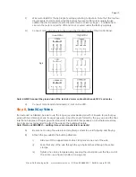
1.5 Sprinkler Systems and Fan Placement


In any installation where fire sprinklers are in place, do not interfere with their correct operation.  Note; fans 
should be located not less than 3 feet below a sprinkler, and placed central to each sprinkler quadrant.  

Our standard variable-speed control system can be connected to a fire suppression control system, which 
will emergency-stop fans in case of fire.  Prior to installing fans, review all codes applicable to sprinkler 
systems and fans to ensure code compliance.  Refer to the wiring diagrams packaged inside the control 
panel for proper installation. If further advice is needed, you may contact our support staff.  However, it is 
your sole responsibility to see that the installation is completed to code and that it is correct. 


1.6 Locating Control Panels


Each fan has its own motor control panel (MCP).  A motor control panel must be mounted at least 5 feet 
outside maximum blade length, and within 25 feet of the fan.  Make sure the lockable service disconnect 
located on the side of the MCP is within line of sight of the motor to comply with OSHA and local safety 
codes.  
 

1.7 Connecting Fans to Remote Controls


You may control one fan or many fans with a single remote control switch box.  The remote switch box 
should be located no more than 100 feet (supplied) from the motor control panel.  Fans may also be 
controled with temperature control sensors and building automation systems.  Contact technical support 
for more information. 
 

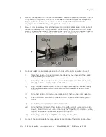
1.8 Shielded Motor Cable 

(For Variable Frequency Drives)


To minimize electromagnetic interference and stray voltage, each MacroAir fan assembly includes 25 feet 

of shielded motor cable, cable glands, and a variable frequency drive with a built-in filter.  The shielded 
motor cable connects the fan motor to the motor control panel.  This system reduces the likelihood of 
electronic-broadcasting and receiving which can interfere with radio and other sensitive equipment.  
Plus, this system cuts fan installation cost as conduit is not needed where shielded cable is used.  For more 
regulatory information on electromagnetic interference (EMI) refer to page 25.  


1.9 Check Federal, State, and Local Codes


Check all relevant codes to make sure all product certifications, product listings, and building regulations 
are met.   Code compliance is the responsibility of the installer. 
 

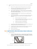
2.0 General Mounting Considerations 

(I-Beam, Glulam Beam, or Other Type of Truss System)


Each type of mounting system (I-beam, glulam, or other) requires a specific mounting bracket.  Most are 
available from MacroAir.  Before installing fans, check with the contractor, building owner, or architect to 
ensure the building structure is sound and will support the weight of the fan.  MacroAir Technologies 
provides guidelines for mounting fans; however, it is the sole responsibility of the building owner and 
installer to ensure the safety of the mounting system, that the building structure is sound, and that the 
installation complies with all federal, state, and local codes. 

Fig 1 

Содержание Airvolution

Страница 1: ...Owners Manual Installation Manual...

Страница 2: ...omponents 7 1 2 Placement and Spacing 7 1 3 Fan Clearance Drawing 7 1 4 Mark Floor To Alert Personnel 7 1 5 Sprinkler Systems and Fan Placement 8 1 6 Locating Control Panels 8 1 7 Connecting Fans to R...

Страница 3: ...ety 17 Step 11 Install Guards If Necessary 18 Step 12 Install Input Power 18 Step 13 Verify Proper Operation 18 3 Installation Procedures For eco6 Guard Fan 20 Step 1 Install Mounting Assembly eco6 20...

Страница 4: ...Page 4 MacroAir Technologies Inc www macro air com Toll Free 866 668 3247 Build January 9 2009 Anatomy of a Fan...

Страница 5: ...arbox Motor with J Box Safety System Universal Mounting Hardware Swivel Mount Assembly 4 Guy Wire Cables 1 8 inch Guy Wire Clamp Kit includes tension tool Safety Cable inch Safety Cable Bolt Pack Blad...

Страница 6: ...creen to motor mount Packet of large sheet metal screws to attach front screen to rear screen Hub cover Screws and star washers to attach hub cover Hub loose in the crate If the fan is ordered without...

Страница 7: ...ll be mounted to determine vertical and horizontal spatial clearances A standard ceiling fan is mounted so the measurement from the bottom of the beam to the bottom of a fan s hub is 3 feet Extensions...

Страница 8: ...controled with temperature control sensors and building automation systems Contact technical support for more information 1 8 Shielded Motor Cable For Variable Frequency Drives To minimize electromagn...

Страница 9: ...e feet of the blade tips when the fan is at rest is considered close clearance It is EXTREMELY DANGEROUS to mount the fans within close clearance of any object We strongly recommend not mounting the f...

Страница 10: ...anel ensure all POWER IS OFF and locked out to avoid injury Control Panel Occasional cleaning is advisable especially when the panel is located in a dusty or dirty environment A can of compressed air...

Страница 11: ...the beam and attach them to the mount using the supplied fasteners For thicker I beams use the supplied shims between the clamp and the mount as shown in figure 3 Note In all cases be sure to thoroug...

Страница 12: ...is extremely important Again do not re use nylon lock nuts Step 3 Attach Safety Cable Refer to figure 4 as necessary This step is required omitting it will void manufacturer s warranty A Slide two of...

Страница 13: ...ing to the wiring diagram on page 28 packaged in the control panel and or the sticker inside the remote enclosure Close up the remote enclosure C Install the other supplied strain relief fitting in th...

Страница 14: ...i Take the cable gland apart and slide the gland nut over the end of the cable threads facing the cable end ii Slide the plastic and rubber cable gland insert over the end of the cable with the large...

Страница 15: ...s If an extension is installed be sure to use the longer guy wires packaged with it Be sure to use four guy wires with two clamps per end four per guy wire Keep the angle formed by the guy wire and th...

Страница 16: ...remains horizontal 1 Attach the tool to a 3 8 inch drive ratchet 2 Loop the tool through the free end of the guy wire between the clamps and turn clockwise as far as possible 3 Tighten the inner clam...

Страница 17: ...securely tighten an included nylon lock nut onto each of the bolts Do not use any washers The safety link will bend when the nut closest to the hub is tightened due to the angle of the hub winglets v...

Страница 18: ...ed inside of MCP Note ALWAYS connect the grounding bar in the MCP to ground at the power panel when pulling power from the main panel be sure to pull a full sized ground D Connect input power leads to...

Страница 19: ...ll cover off the VFD Ensure that the wiring matches the wiring diagram this can be found on the included control panel drawing as well as on a sticker inside the control panel door If this wiring is w...

Страница 20: ...sonry walls i Insert Red Head or equivalent 1 2 self anchoring studs not included into the mounting holes properly securing them according to manufacturer s instructions ii Slide the mount plates over...

Страница 21: ...on the mounting assembly making sure the mount assembly pivot section is flat B Rotate the motor assembly to approximately the desired horizontal angle Make sure to leave enough room to use at least...

Страница 22: ...ear B Line up the holes in the screen struts with the holes in the motor mount plate C Securely attach the screen to the motor mount plate using the supplied bolts washers and nylon lock nuts being su...

Страница 23: ...ch Fan Blades For fans without safety screens blade safety links and safety link extenders must be installed See step 9B in the standard instructions page 16 for more information on how to install the...

Страница 24: ...n Always allow one to two inches of clearance between the safety screen and walls or ceiling C Check that all nuts and bolts are completely tight D Thread the safety cable through the center hole on t...

Страница 25: ...However there is no guarantee that interference will not occur in a particular installation If MacroAir products fans do cause interference with radio communications services which can be determined...

Страница 26: ...Page 26 MacroAir Technologies Inc www macro air com Toll Free 866 668 3247 Build January 9 2009 Multiple Fan Wiring Diagram...

Страница 27: ...Page 27 MacroAir Technologies Inc www macro air com Toll Free 866 668 3247 Build January 9 2009 Mounting Dimensions Diagram...

Страница 28: ...Page 28 MacroAir Technologies Inc www macro air com Toll Free 866 668 3247 Build January 9 2009 Motor Control Panel And Assembly Drawing...

Страница 29: ...e photocopied reproduced or translated to another language without the prior written consent of MacroAir Technologies Inc The information in this document is subject to change without notice MacroAir...

Отзывы: