


Page
21
MacroAir Technologies Inc. www.macro-air.com Toll Free: 866-668-3247 Build: January 9 2009
For Pole-Mounted Applications
A)
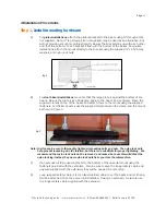
Cut and mount bracketing.
i)
Cut and assemble UniStrut or equivalent bracketing (not included). Use the
mount assembly as a template for length and hole spacing.
ii)
Securely attach the brackets to the pole at the desired height. Be sure that all
strap bolts are firmly tightened and that the vertical spacing is correct.
B)
Attach the fan to the bracketing.
i)
Insert 1/2” bolts with 1 washer each into the brackets.
ii)
Slide the mount assembly over the bolts and attach using nylon lock nuts and flat
washers.
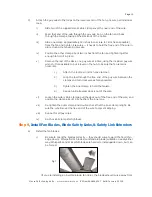
Step 2
, Attach Motor Assembly To Mounting Assembly
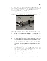
A)
Place the motor assembly on the mounting assembly, making sure the mount assembly
pivot section is flat.
B)
Rotate the motor assembly to approximately the desired horizontal angle. Make sure to
leave enough room to use at least three mounting bolts.
C)
Insert supplied 1/2” mounting bolts and washers downward through holes. Securely
tighten the provided nylon lock nuts, using washers to maximize hold. Four mount bolts
are best, but at least three (3) mounting bolts must be used.
Step 3
, Make Control And Motor Cable Connections
A)
For variable-speed fans, set up the Motor Control Panel and Remote Switchbox
according to the instructions found in Step 4 through Step 7 of the regular instructions
(pages 12 through 15).
B)
For single-speed fans, wire up the included circuit breaker/starter according to the
instructions printed on the inside of the box.
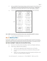
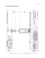
C)
For either fan, use the wiring diagrams in figure 12 (next page) to make the proper
Fig 11
Содержание Airvolution
Страница 1: ...Owners Manual Installation Manual...


