IM213D-MC Issue 10 © 2017
Page 1 of 8
INSTRUCTION MANUAL
To the Owner
POSITIVE DISPLACEMENT FLOWMETER
Important Information
PLEASE READ THIS INFORMATION CAREFULLY
BEFORE USE.
Read and retain this instruction manual to assist you
in the operation and maintenance of this product.
If you have any problems with the meter, refer to the
maintenance and trouble shooting sections of this
manual.
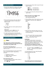
This manual contains connection and operating
instructions for meters with Liquid Crystal displays
(LCD).
If you need further assistance, please contact your
local representative or distributor for advice.
Operating Principle
WARNING
This Flow Meter has incorporated the oval rotor
principal into its design. This has proven to be a
reliable and highly accurate method of measuring
flow.
Exceptional repeatability and high accuracy over a
wide range of fluid viscosities and flow rates are
features of the oval rotor design. With a low pressure
drop and high pressure rating oval rotor flow meters
are suitable for both gravity and pump (in line)
Before use, confirm the fluid to be used is
compatible with the meter. Refer to Industry
fluid compatibility charts or consult your local
representative for advice.
When fluid passes through the meter the rotors
turn, as shown below. The magnets which are
located in the rotors will pass across the PCB
sensors.
A signal is generated which is then sent by the PCB
to the relevant LCD, or receiving instrument as a
Pulse Output.
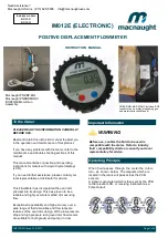
IM012E (ELECTRONIC)
Includes m odels
IM012E-01
IM012E-02
Need Assistance?
Macnaught USA Inc (813) 628-5506 [email protected]
Macnaught PN# BP-MG
Macnaught PN#BP-MGHV
BOP20/60 Meter Gun
Assembly
PN# BP-MG
& BP-MGHV
includes: BOP
connector
hose, meter, dispensing gun
and meter Instruction Manual


