MACKISSIC RT1450IC Скачать руководство пользователя страница 10


10 


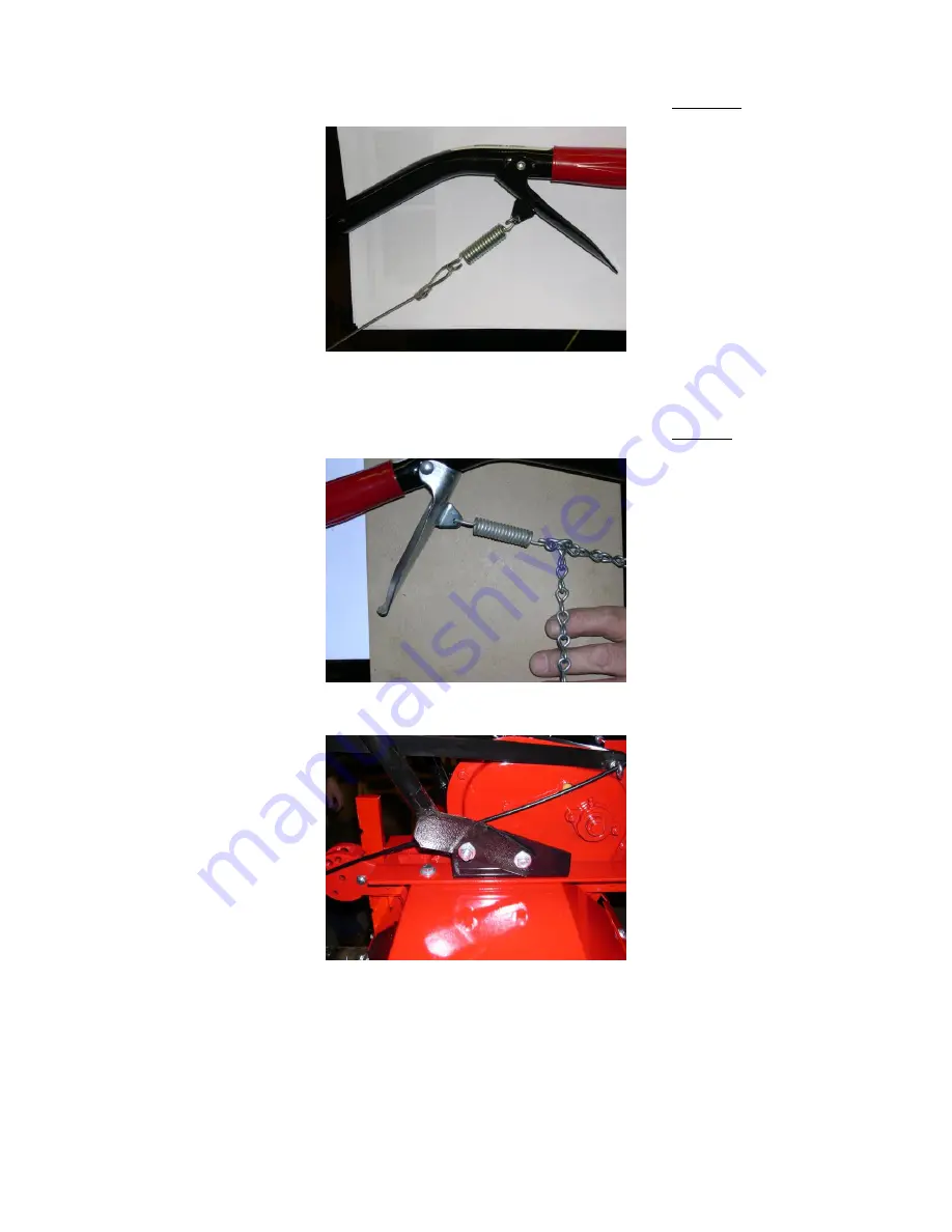
7.  Attach the clutch spring to the end of the tine engage cable.  Attach the clutch control lever using a  

1/4-20 x 1-

1/2” HHCS and a 1/4-20 nylock nut.  Attach the clutch spring to the right hand handle. 


8.  Identify the wheel engage cable.  This is the cable that attaches to the front idler arm near the engine. 


9.  Attach the clutch spring to the 10

th

 link from the end of the chain.  Attach the clutch control lever using a  

1/4-20 x 1-

1/2” HHCS and a 1/4-20 nylock nut.  Attach the clutch spring to the left hand handle. 


10.  Attach the rear handle bar mount hole to the handle bar mount bracket. 


Содержание RT1450IC

Страница 1: ...ERRY REAR TINE TILLER RT1450IC RT83H OWNER S MANUAL MACKISSIC INC P O BOX 111 PARKER FORD PA 19457 Phone 610 495 7181 e mail info mackissic com FAX 610 495 5951 www mackissic com P N 712 0078 05 11 17...

Страница 2: ...ng DANGER Rotating tines and belt Keep hands and feet out of tines and belt area while machine is running DANGER This machine can CRUSH CUT and SEVER parts of your body if they enter the operating are...

Страница 3: ...3 MAKE CERTAIN THAT ALL SAFETY LABELS ON THIS EQUIPMENT ARE KEPT CLEAN AND IN GOOD CONDITION IF YOU NEED REPLACEMENT LABELS PLEASE ORDER BY PART NUMBER PART 091 0057 PART 091 0070 PART 091 0085...

Страница 4: ...and pull starter rope Reduce throttle speed As engine starts move choke lever to RUN Place shift arm in R reverse position Move throttle to desired speed Engage left hand lever to engage wheels TILLIN...

Страница 5: ...ghten to assure continued safe operation Handle fuel with care it is highly flammable Refer to engine manual for safety and service instructions Disengage tines and wheels before starting the engine m...

Страница 6: ...unit to cool at least five minutes before storing Before cleaning repairing or inspecting stop the engine and make certain the tines and all moving parts have stopped Disconnect the spark plug wire an...

Страница 7: ...covered or grass covered land unless the engine s exhaust system is equipped with a spark arrester meeting applicable local or state laws if any If a spark arrester is used the operator should mainta...

Страница 8: ...1 EA 5 16 18 X 5 EYE BOLT 090 0268 RH HANDLE 1 EA 3 8 24 HEX NUT 090 0267 SHIFT ROD 2 EA 1 4 20 X 1 1 2 HHCS 090 0057 CLUTCH CONTROL LEVERS 2 EA 1 4 20 NYLOCK NUT 090 0470 CLUTCH CONTROL LEVERS TOOLS...

Страница 9: ...the left and right hand handles to the front hole of the handle mount brackets 5 Attach the cross brace to the handlebars using the upper hole in the cross brace Be certain to place two 5 16 flat was...

Страница 10: ...d handle 8 Identify the wheel engage cable This is the cable that attaches to the front idler arm near the engine 9 Attach the clutch spring to the 10 th link from the end of the chain Attach the clut...

Страница 11: ...this order the handle bar tie bar cross brace Hand tighten with a nylock nut 12 Attach the throttle control to the left hand handle 13 Tighten all the hardware used for assembly in steps 2 thru 12 14...

Страница 12: ...he shift rod through the eyebolt and screw it into the rod end attached to the upper shift arm Make sure that the handle end of the shift rod points down and then tighten the jam nut on the end of the...

Страница 13: ...y from the area of the spill Avoid creating any source of ignition until gasoline vapors have disappeared CAUTION Experience indicates that alcohol blended fuels gasohol ethanol methanol can attract m...

Страница 14: ...difficult and hard soil the drag bar should be reversed with the straight end down This will provide additional resistance which is necessary for digging in these conditions Once the ground has been...

Страница 15: ...1 Release both handle levers 2 Place shift arm in N neutral position 3 Move throttle to slow or stop position 4 Turn engine switch to OFF if so equipped Reverse 1 Release both handle levers 2 Check b...

Страница 16: ...inspected periodically Belt Adjustment 1 To adjust the front belt coming off the engine loosen the engine from the engine mount weldment and slide it forward or backwards Before tightening make sure...

Страница 17: ...sable to take your tiller to an authorized MERRY TILLER dealer especially if there are signs of excessive wear Following are some suggestions that will help to determine the amount of wear Before remo...

Страница 18: ...re maximum engine and tiller life The engine will normally consume oil so check oil level regularly and before each use TIME TO CHANGE THE TINE SHAFT SEALS Tine Shaft Seal Replacement Instructions It...

Страница 19: ...tine shaft and drive shaft for up and down play if loose replace bearings If transmission is OK replace tine shaft and drive shaft seals Inspect tines for wear if cutting corner is rounded replace tin...

Страница 20: ...el lines and carburetor are empty Never use engine or carburetor cleaner products in the fuel tank or permanent damage may occur Remove the spark plug pour approximately one tablespoon of engine oil i...

Страница 21: ...21 SECTION VII PARTS BREAKDOWN...

Страница 22: ...ION MOUNT ASSEMBLY 4 SEE PAGE 35 1 AXLE TIRE ASSEMBLY 5 712 0056 1 BELT GUARD 6 712 0044 1 INNER BELT GUARD 7 SEE PAGE 31 1 TINE SHIELD ASSEMBLY 8 090 0111 4 3 8 16 X 1 1 4 HHCS 9 090 0234 4 3 8 USS F...

Страница 23: ...23...

Страница 24: ...5 1 3 16 X 3 16 X 1 1 2 KEY 8 712 0007 1 REAR DIRVE MOUNT WELDMENT 9 090 0438 1 5 16 18 J NUT 10 090 0088 7 5 16 18 X 1 HHCS 11 708 3293 1 6 PULLEY 12 030 0012 1 2 3V8 0 SHEAVE 13 030 0247 1 4H500 BEL...

Страница 25: ...25...

Страница 26: ...USS FLATWASHER 14 090 0112 4 3 8 16 X 1 1 2 HHCS 15 712 0185 1 TRANSMISSION ASSY SEE PG XX 16 712 0140 1 DRAG BAR WELDMENT 17 712 0070 1 LH OUTSIDE TINE ASSY 18 712 0099 1 LH INSIDE TINE ASSY 19 090 0...

Страница 27: ...27...

Страница 28: ...HEX NUT 5 712 0166 1 TRANSMISSION SHIFT ROD 6 712 0164 1 TRANSMISSION SHIFT ARM 7 090 0060 1 20 X 1 HHCS 8 090 0630 1 3 8 24 NYLOCK NUT 9 090 0233 1 5 16 USS FLATWASHER 10 090 0470 1 20 NYLOCK NUT 11...

Страница 29: ...29...

Страница 30: ...TINE SHIELD SKIRT 5 712 0043 2 TINE SHIELD TOP BRACE 6 712 0039 1 TINE SHIELD DIRT DEFLECTOR 7 712 0040 1 TINE GUARD FLAP 8 712 0041 1 2 HINGE 9 090 0012 20 20 X HHCS 10 090 0060 2 20 X 1 HHCS 11 090...

Страница 31: ...31...

Страница 32: ...2 0167 1 BOTTOM HOUSING BRACKET 11 712 0172 1 LOWER SHIFT WELDMENT 12 090 0632 1 3 8 X 3 8 SOCKET HEAD SHOULDER BOLT 13 712 0135 1 IDLER ARM 14 090 0418 4 5 16 18 WHIZ NUT 15 090 0233 8 5 16 USS FLATW...

Страница 33: ...33...

Страница 34: ...MBLY ITEM PART QTY DESCRIPTION 1 090 0604 2 3 8 16 X 2 1 4 HHCS GR8 2 712 0072 1 RH WHEEL 3 712 0019 2 WHEEL SPACER 4 030 0246 2 DRIVE SHAFT BEARING 5 712 0020 1 DRIVE AXLE WELDMENT 6 712 0073 1 LH WH...

Страница 35: ...35...

Страница 36: ...81 1 LH HANDLE ASSEMBLY 7 090 0400 2 10 32 X 1 1 4 RHMS 8 712 0087 1 WHEEL ENGAGE CABLE 9 710 1848 2 CLUTCH SPRING 10 706 3254 2 CLUTCH CONTROL LEVER 11 712 0126 1 THROTTLE CONTROL 12 706 1539 2 10 32...

Страница 37: ...37...

Страница 38: ...38...

Страница 39: ...39...

Страница 40: ...40...

Страница 41: ...assembled or installed as specified in the owner s manual The warranty does not cover any product that has been altered or modified In addition the warranty does not extend to repairs made necessary b...

Отзывы: