background image

9

Quick-Start Guide

Quick

-Star

t Guide

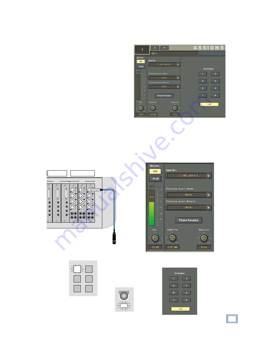
5.  Make sure channel 1 has Input 1 assigned to it. 

Open the Assign window (Windows > Assign). 
Under the Input Src drop-down box select Mic 
Line In. 1. 

6.  If the microphone requires phantom power, 

select the 48V button in the Assign window to 
turn on phantom power. Leave the –10 dB pad 
off when using a microphone.

7.  Talk or sing into the microphone and adjust the 

Gain control using the V-Pot on channel 1 so 
the meter indicates between –12 and –6.

8.  In the Assign window, make sure L-R is select-

ed under Bus Assigns.

Getting Sound Happening

The following procedure demonstrates how to 

connect a microphone to an input and get sound out 
of the Digital X Bus.

Here’s what you’ll need:

• 

1 stereo power amplifi er

• 

1 pair of monitor speakers (you can substi-
tute a pair of powered monitors for the power 
amplifi er/monitor speaker combo, or a set of 
stereo headphones)

• 1 

microphone

• 

Appropriate cable to connect the microphone to 
your particular input card

• 

Cables to connect the speaker outputs to the 
amplifi er or powered monitor speakers

Here's what you do:

1.  Turn on the Digital X Bus.

2.  Connect a microphone to Input 1. If you are us-

ing a MIC/LINE 8 card, use a DB25-to-XLR fe-
male breakout cable to connect the microphone 
to Input 1. If you are using a MIC/LINE 4 card, 
you can plug the XLR microphone cable directly 
into the card.

DIGITAL CARD

OPTICAL

TDIF

I/O

IN A

IN B

OUT A

OUT B

DIGITAL CARD

OPTICAL

TDIF

I/O

IN A

IN B

OUT A

OUT B

GITAL CARD

CAL

F

O

IN A

IN B

UT A

UT B

MIC/LINE 4 CARD

5

7

6

8

1

2

3

4

MIC/LINE 4 CARD

5

7

6

8

1

2

3

4

MIC/LINE 4 CARD

5

7

6

8

1

2

3

4

B • SLOTS

A • SLOTS

THREE

MIC/LINE 4 CARDS

THREE

DIGITAL CARDS

3.  Press the Bank 1 button (1-24) in the Banks sec-

tion of the console (just above the Master fader).

GROUPS

49-72

MIDI

MSTRS

25-48

1-24

4.  Press the SELECT button on channel 1.

SELECT

Содержание X.200

Страница 1: ...QUICK START GUIDE X 200...

Страница 2: ...ARD 5 8 SYNCCARD 6 OtherConnections 6 9 FOOTSWITCH1and2 6 10 SERIAL9PIN 6 11 MIDIINandOUT 6 12 ETHERNET 6 13 USB 6 14 IECPowerReceptacle 6 15 PowerSwitch 7 MoreConnections 7 16 Mouse 7 17 Keyboard 7 1...

Страница 3: ...for future reference i e insurance claims tech support return authorization etc Purchased at Date of purchase Thank you for choosing a Mackie Digital X Bus for your next generation digital recording...

Страница 4: ...x B in the Digital X Bus X 200 Owner s Manual for a wiring diagram of these connectors Once you ve unpacked your new Digital X Bus you ll want to posi tion it where you can sit comfort ably and reach...

Страница 5: ...card to find out if it supports the double fast or single wire method 6 FIREWIRE CARD The FireWire card uses the IEEE 1394 protocol for connecting digital devices It currently provides 24 inputs and...

Страница 6: ...when connecting to equipment with transport con trols and a position display The MIDI connectors can also be used to control your DAW application when the MIDI fader bank is selected DAW Bank You can...

Страница 7: ...These are connections to the motherboard and include four additional USB connections and the PS 2 style mouse and keyboard connections To access the connectors 1 First turn off the Digital X Bus sele...

Страница 8: ...ns are a row of rotary con trols called V Pots which is short for virtual potenti ometer Again unlike an analog console where a rotary pot can control one function a digital console allows you to assi...

Страница 9: ...he power amplifier monitor speaker combo or a set of stereo headphones 1 microphone Appropriate cable to connect the microphone to your particular input card Cables to connect the speaker outputs to t...

Страница 10: ...ufacturers recommended setting 17 Talk or sing into the microphone while slowly turning up the level control in the CONTROL ROOM sec tion You should hear sound in the speakers and see the L R meters a...

Страница 11: ...n 23 In the AUTOMATION MODES section of the console select FADER and MUTE Turn off the BYPASS button AUTOMATION MODES TRIM PAN ALL BYPASS FADER MUTE 24 Select the WRITE button in the ASSIGN BUT TON SE...

Страница 12: ...In this case you might have three MIC LINE 4 CARDS installed in slots 1 3 A SLOTS for 24 analog inputs and three DIGITAL CARDS installed in slots 4 6 B SLOTS for 24 digital outputs By assigning the Ou...

Страница 13: ...NG M G MAN F FIGURE E P PAT ATENT P T PENDING ENGINEERED BY D BY SYNC C SLOTS D SLOT B SLOTS A SLOTS MIDI IN FOOT SWITCH 1 2 MIDI OUT USB ETHERNET SERIAL 9 PIN 1 15V 9 V 9amp 6 p 60Hz 230V 4 5 V 4 5am...

Страница 14: ...NG A G ARE T E TRADEMARKS O S OR R R REGISTERED T D TRADEMARKS O S OF L F LOUD T D TECH I H INC C TA TAPCO MACKIE A AND T D THE E RUNNING M G MAN F FIGURE E P PAT ATENT P T PENDING ENGINEERED BY D BY...

Страница 15: ...z 230V 4 5 V 4 5amp 5 p 50Hz 1100 1100W M W Max Bass Guitar Direct Box Electric Guitar Aux Sends Channel Inserts or Master Inserts Returns Internal Effects Rack From Aux Sends Channel Inserts or Maste...

Страница 16: ...ed Road NE Woodinville WA 98072 USA www mackie com sales mackie com United States and Canada 800 898 3211 Europe Asia Central and South America 425 487 4333 Fax 425 487 4337 Middle East and Africa 31...

Отзывы: