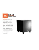
8
POWER
SIGNAL PRESENT
INPUT
THRU
THERMAL
PEAK
TIMED TURNOFF
ON
OFF
CONTOUR
LOW CUT
ON
75Hz
12k/AIR
100Hz
+3dB
MIC
LINE
LEVEL
(+4dBu)
NORMAL
+40dB
O
O
O
PARALLEL
REAR PANEL DESCRIPTION
5. THERMAL Indicator
This LED lights if the heatsink temperature exceeds a
safe operating temperature and triggers the thermal safety
switch. In the unlikely event that this occurs, the built-in
amplifiers shut down until the heatsink temperature cools
back down. Then the thermal switch resets itself, the THER-
MAL indicator turns off, and normal operation resumes.
If the SRM450v keeps shutting down,
make sure there is plenty of ventilation
to the rear panel. Please see “Thermal
Considerations” on page 1.
6. CONTOUR
Pushing in this switch engages a filter that provides dB
of boost to the low and high frequencies (below 100 Hz
and above 1 kHz). This provides a punchy, crisp sound
for most live music applications. You can experiment with
this switch by leaving it out for a while, then pushing it in
to determine which way sounds best for your application.
It is especially useful when listening at lower volumes, as
it highlights the bass like a Loudness switch, in addition to
boosting the highs.
7. LOW CUT
Pushing in this switch engages a low-cut filter, which rolls
off the low frequencies below 75 Hz. This is useful for mini-
mizing stage noise (rumble) and microphone handling noise.
It is highly recommended that you engage this switch
when using the SRM450v as a stage monitor. This allows
the bass amplifier to utilize its power for those frequencies
useful in stage monitor applications.
The SRM450v has several connectors, controls, and
indicators that you should understand.
1. IEC Socket
This is where you connect the supplied AC linecord to
provide AC power to the SRM450v’s built-in power amplifi-
ers. Plug the linecord into an AC socket properly configured
for your particular model.
Note:
If you happen to lose the AC linecord, replace-
ments are readily available at any office or computer supply
store. Always use a three-pin plug with a ground pin.
2. POWER Switch
Switch up to turn the SRM50v on. Make sure the LEV-
EL control is down before you turn it on. Press the bottom
of this switch to put the speaker into standby mode. It will
not function, but the circuits are still live. To remove AC
power, either turn off the AC mains supply, or unplug the
power cord from the speaker and the AC mains supply.
3. POWER ON Indicator
When the POWER switch is turned on, and the linecord
is connected to an active AC Mains supply, this indicator, lo-
cated just above the POWER switch, glows to let you know
that you’re ready to rock and roll. The cool blue LED on the
front of the speaker works in the same way.
4. TIMED TURNOFF
When this switch is pushed in, the built-in amplifiers turn
on and off depending on the presence or absence of an input
signal. An input signal level of –45 dBu (minimum) activates
the auto-on function. A silent period greater than three
minutes activates the auto-off function. The blue LED on the
front of the speaker reflects the state of the amplifiers.