background image

(Yaskawa Motors)


Run the motor cables (encoder and power) from the motors to the back panel or enclosure. If the machine was

equipped with CNC components before the upgrade the cables can usually follow the path of the old motor cables.

Take care when running the cables to keep them away from pinch points and sharp edges. The cables are protected by

robust insulation but repeated wear and tear will cause damage and eventual failure. If the cables must run over a

possible wear point, use some form of loom for additional protection. Keep in mind the motion of the machine and

possible cable snag points while the machine is moving.

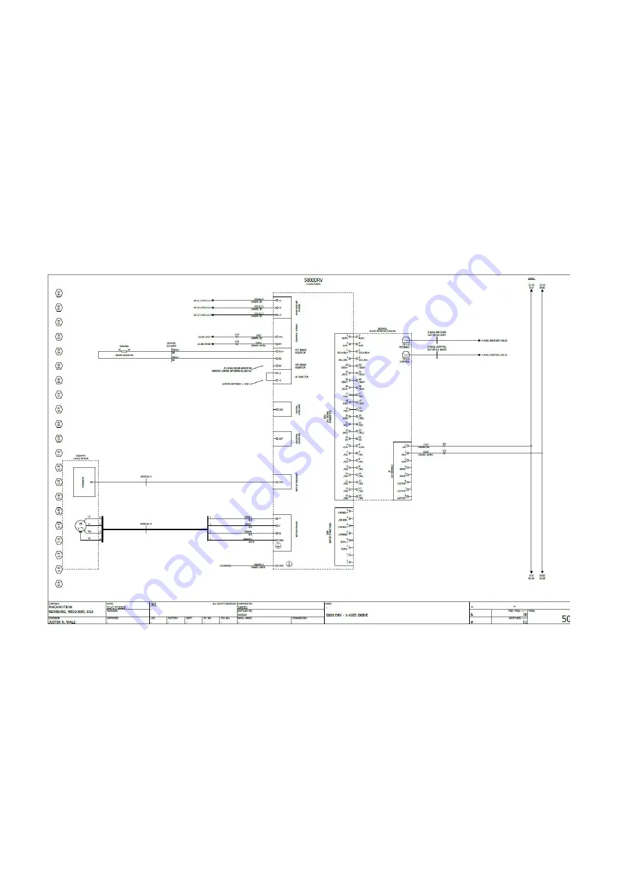
There are several different variations for connecting the motor cables to the servo drives. Please review the schematic

that was sent to you by MachMotion.

There are several different variations for connecting the motor cables to the VFD. Please review the schematic that was

sent to you by MachMotion.

Run Cables

Route Motor Cables

Connect Cables to Servo Drives

Wire Spindle Motor to VFD

Содержание 2000 Series

Страница 1: ...e following manual as your guide to locate and mark the old wiring remove the original system and install the new MachMotion complete system If you need clarification please contact MachMotion technic...

Страница 2: ...al transformer 2 Remove the old cables running to the motors 1 Mount the new electrical enclosure to the machine or if you just received a back panel it must be mounted similar to the image below Back...

Страница 3: ...rom the back of the control Run conduit from the control to the back panel or electrical enclosure 2 Connect ethernet cables power connector cable and E stop cables into the control as shown below If...

Страница 4: ...1 If using a RapidPath Motion Controller connect the light blue EtherCAT cable into N2 on the CTB servo drive Connect Cables to the Back Panel...

Страница 5: ...RapidPath Motion Controller 2 Connect the green Machine Network cable into the VFD or the network switch Yaskawa VFD...

Страница 6: ...r local network if you do not plan to use the built in WiFi Internet is not necessary to run the control However assistance from our support team will be greatly limited without access to the internet...

Страница 7: ...l E stop into the 24V block and the other side into the blank terminal block Then connect the red wire from the control E stop into the blank terminal block as well Finally put the black wire from the...

Страница 8: ...ded due to different styles of machines If possible take a look at the gears and write down the number of teeth on the motor gear and the ball screw gear If you write down the gear ratio specification...

Страница 9: ...ge and eventual failure If the cables must run over a possible wear point use some form of loom for additional protection Keep in mind the motion of the machine and possible cable snag points while th...

Страница 10: ...comes pre jumpered to the 120v circuit to the left of output wiring block as shown below Verify the voltage of each output destination before wiring If any of your outputs run on 24VDC make sure the...

Страница 11: ...Wiring Lube System For a contactor with 120VAC coil wire it as shown Wiring Coolant System...

Страница 12: ...your machine You can power up to a 0 5 hp 3 phase coolant motor To run a 3 phase motor the back panel will have to be powered with 3 phase Run 3 wires from 2L1 2L2 and 2L3 on the top of the back panel...

Страница 13: ...Wiring Tool Setter Wiring Probe...

Страница 14: ...click Configure Mach and then click on theMotors Select the problem motor and check the Reverse check box 3 Test inputs and outputs The best way to do this is use the buttons already setup for the in...

Страница 15: ...move the machine with the jog functionality or pendant if the speed is turned down and caution is used The softlimits wizard will go through the three axes in order X Y Z and ask you to move the mach...

Страница 16: ...When the limit is reached the machine will cease moving in that direction It is a good idea to turn down the jog rate and test the limits at this point To set the units for each axis the pitch of the...

Страница 17: ...for all mechanical deficiencies The wizard supplies buttons for moving the machine positive and negative 1 inch input for the amount of error and an indication of direction of error Backlash Be sure...

Страница 18: ...cifications from the spindle and insert them into the wizard The information needed is the maximum RPM for low gear the maximum RPM for high gear and the amps for full load These should be input and t...

Страница 19: ...elect Manual Calibration 2 Select Commanded Distance 3 Input 1 in the Distance to move axis field If the machine is setup with metric units enter25 4 instead 4 For each axis do the following 1 Setup a...

Страница 20: ...o the max range Take the max and min RPM for each gear range in input them in the gear range settings shown below You can access this screen by going to Configure Control Spindle Most machines will ne...

Страница 21: ...that came with your cabinet It is either a Yaskawa V1000 That will bring up the editable parameters shown in the lower red box below Simply highlight the value to change it Many of these values may b...

Страница 22: ...he 2000 Series HMI Human Machine Interface manual For information about MachMotion Software Operation please see 2000 Series Mill Router Operating Manual MachMotion warranty policy is subject to chang...

Отзывы: