background image

40M COIL ASSEMBLY  

INSTRUCTIONS 

STEP 1: 


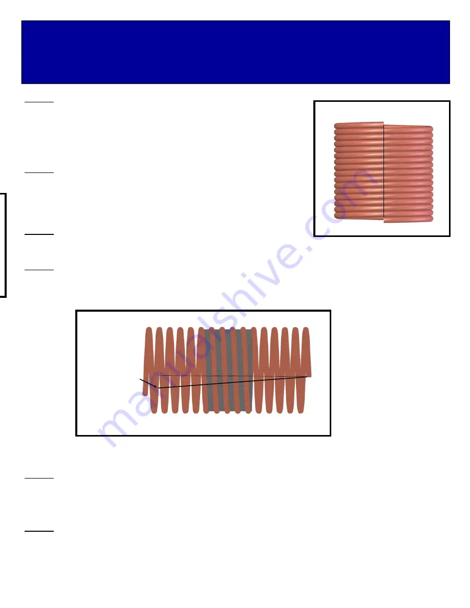
The coil comes wound tight with 16 total turns from the factory. The excess 

material will be trimmed off after the coil is in its final position.  Using a permanent  
marker, draw a straight line from one end of the coil to the other. This will help later 
to determine if your coil has grown in diameter during assembly. After final position-
ing of the coil no more 3/4 of an inch of line tilt is allowed. A larger coil will cause the 
inductance to change which can cause your antenna to be off frequency.  
 

STEP 2: 

The COIL is wound tight at the factory to prevent damage during shipping. Use the 
COIL SPREADING TOOL provided, and carefully insert it into the first turn of the 
COIL. Now gently push or roll the tool through all 16 turns of the COIL. Now the 
COIL is nearly in its final shape and is ready to be threaded onto the COIL SUP-
PORT. Note the reference line drawn earlier, it will have a slight tilt after spreading. 
 

STEP 3: 


On one end, use pliers to gently straighten the last 1/2” of the COIL and file 

off any burrs.  
 

STEP 4:


Begin threading the COIL onto one end of the COIL SUPPORT. 

BE CAREFUL 

to not deform the COIL during this 

process. The COIL should thread smoothly. Continue until about 5-1/2 turns are past the COIL SUPPORT or close to the 
center. Exact centering is not important. Again, note your reference line. 


NOTE:  PENETROX PASTE FOR LUBRICATING SCREW THREADS AND TUBING JOINTS HAS BEEN SUPPLIED. USE A VERY SMALL AMOUNT ON 
EACH SCREW THREAD AND UNDER THE COIL POSTS DURING THE NEXT OPERATION.


STEP 5:


Insert the COIL INSULATOR (M2AFG0050) into your COIL SUPPORT (M2ACA1554). Rotate the COIL and the 

COIL SUPPORT so the leading end of the COIL goes over and just past the inner hole in the COIL INSULATOR. Now slide 
on one COIL POST on to one end of the COIL so it is right over the first hole. Next, carefully slide on the ELEMENT SEC-
TION #6 (M2AEP40MC-6) and align it so both holes in the tube match the two holes in the COIL INSULATOR.  
 

STEP 6:


Insert hardware through the ELEMENT SECTION #6 and the COIL INSULATOR and begin threading it into the 

COIL POST.  Tighten hardware. Thread the SET SCREW into the top of the COIL POST and with about 1/2” of wire protrud-
ing past the COIL POST, tighten the SET SCREW gently. Use supplied ALLEN WRENCH to tighten the SET SCREW.  


1/2” TO 3/4” 

TILT 

Содержание 40M3C

Страница 1: ...ES The new 40M3C is a new exciting antenna M2 engineers developed a new coil using 3 16 copper wire with an aluminum core The result is a lightweight inductor with great power handling and a Q near 10...

Страница 2: ...cess to meet specific site requirements A quick review of the assembly drawings should help firm up the appropriate strategy Please remember to double check all hard ware for tightness BEFORE it becom...

Страница 3: ...4 ELEMENT SECTION 3 M2AEP40MC 3 ELEMENT SECTION 5 M2AEP40MC 5 ELEMENT TIP SAEL40MCDD LENGTH VARIES DEPENDING ON ELEMENT 2 QTY SCREW 8 32 X 1 LOCK NUT ELEMENT SECTION 6 M2AEP40MC 6 COIL ASSEMBLY ELEMEN...

Страница 4: ...A1550 COIL SUPPORT M2ACA1554 COIL INSULATOR M2AFG0050 COIL POST M2ACA1551 QTY 2 ELEMENT SECTION 6 M2AEP40MC 6 COIL END CAP M2ACA1552 QTY 2 ELEMENT SECTION 4 M2AEP40MC 4 NOTE COVER REMOVED FOR ILLUSTRA...

Страница 5: ...P 4 Begin threading the COIL onto one end of the COIL SUPPORT BE CAREFUL to not deform the COIL during this process The COIL should thread smoothly Continue until about 5 1 2 turns are past the COIL S...

Страница 6: ...The distance between each turn should be the same as the COIL diameter Once the COIL is straight and aligned tighten the final SET SCREW securely STEP 9 Slide COIL COVER and COIL END CAPS onto COIL A...

Страница 7: ...l amount of PENTROX Refer to the drawing below and assemble BOOM SECTIONS as shown Insert hardware and tighten STEP 12 Add the eye bolts into the open hole on boom sections 1 4 SCREW 1 4 20 X 3 1 2 LO...

Страница 8: ...water will help in assembly 40M3C ELEMENT MOUNT ASSEMBLY INSTRUCTIONS BOLT 1 4 20 X 2 3 4 LOCKNUT 1 4 20 QTY 4 ELEMENT MOUNTING PLATE M2AEC0040 QTY 2 ELEMENT CENTER SPLICE M2ASR0050 ELEMENT MOUNT ASS...

Страница 9: ...ELEMENT TIP for the appropri ate element then mark the element assembly to avoid confusion later See GENERIC COMPRESSION CLAMP DETAIL page for more detail STEP 21 Tensioning the element over head guy...

Страница 10: ...M2ADP6675 QTY 2 SHORTING BAR M2AHP0262 SPACER 3 8 X 1 M2ASR0010 BAND CLAMP 52 W HOLE BOLT 1 4 20 X 2 AND LOCKNUT SET SCREW 1 4 20 X 1 4 QTY 2 ELEMENT MOUNTING PLATE M2AEC0040 QTY 2 ELEMENT MOUNTING P...

Страница 11: ...s of each element and lightly tighten STEP 24 Standing at one end of the antenna sight down the boom and reference each element to one another making sure each element is parallel to one another make...

Страница 12: ...7 300 MHz RELECTOR 52 50 47 50 45 50 DRIVEN ELE 39 50 35 50 33 00 DIRECTOR 1 34 50 30 50 28 50 HAIR PIN SHORT BAR POSITION 55 00 55 00 55 00 DRIVEN ELEMENT DIRECTOR ELEMENT SEE CHART THE HAIR PIN SHO...

Страница 13: ...GENERIC COMPRESSION CLAMP DETAIL...

Страница 14: ...fter final adjustments of knots and lock blocks use electrical tape to tape the excess rope down to the main rope as prevention for rope slippage LOCK BLOCK AND KNOT DETAIL LOCK BLOCK ROPE ROUT DETAIL...

Страница 15: ...T0070 1 PENETROX ZINC PASTE CUP 1 ASSEMBLY MANUAL 1 BAG 1 40M COIL 15 1 2 TURNS M2ACA1550 6 COIL POST 500 X 500 X 1 187 ALUMINUM M2ACA1551 12 COIL END CAP 3 625 X 625 UMHW M2ACA1552 12 COIL COVER 3 29...

Отзывы: