WL40EW2F
5-2-55, Minamitsumori, Nishinari-ku, Osaka 557-0063 JAPAN
Phone: +81(6)6659-8201 Fax:
+81(6)6659-8510 E-mail: [email protected]
EM-9080-A P. 7 / 8
■
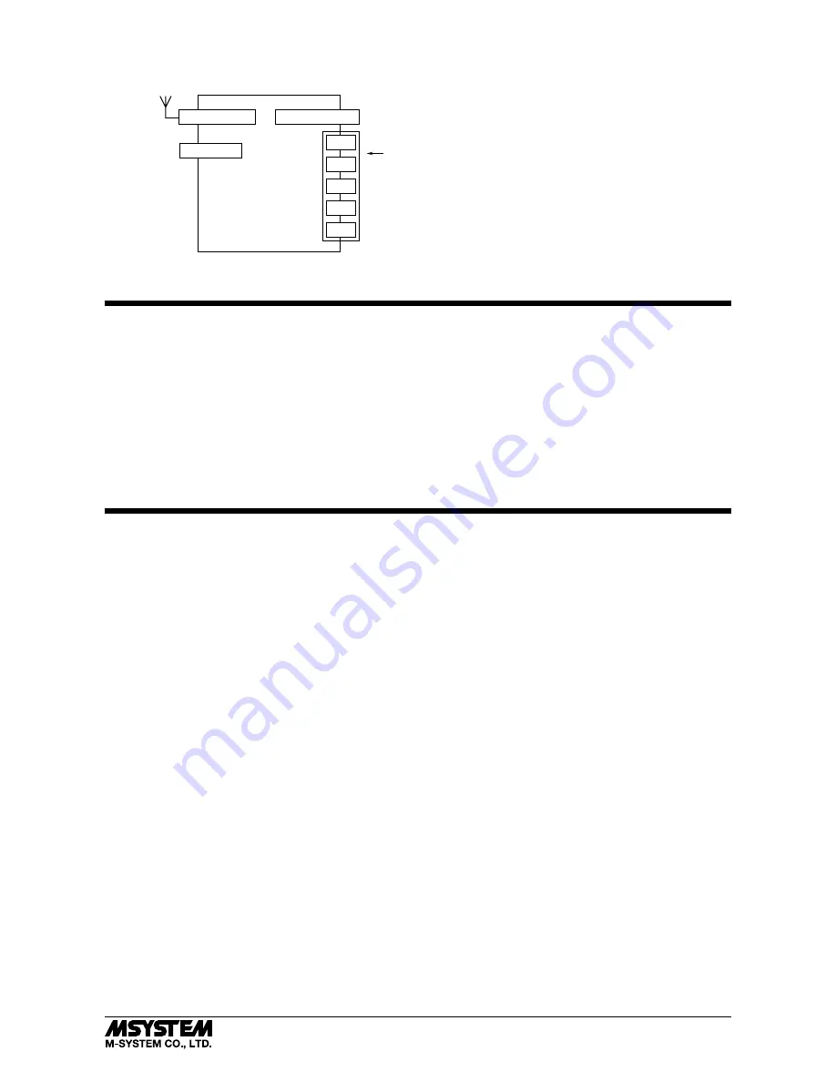
CONNECTION DIAGRAM
Power Input
Maintenance
Connector
To Other
Ethernet Devices
*
Power input defers depending on the power input code you select.
RJ-45 Modular Jack
USB Connector
Antenna Connector
NC
NC
FE1
0V
24V
*
WIRING INSTRUCTIONS
■
TENSION CLAMP (FRONT TWIN CONNECTION) FOR POWER INPUT
Applicable wire size
: 0.2 to 2.5 mm
2
Stripped length
: 10 mm
Recommended terminals:
AI0,25-10YE 0.25 mm
2
(Phoenix Contact)
AI0,34-10TQ 0.34 mm
2
(Phoenix Contact)
AI0,5-10WH 0.5 mm
2
(Phoenix Contact)
AI0,75-10GY 0.75 mm
2
(Phoenix Contact)
AI1-10RD
1.0 mm
2
(Phoenix Contact)
AI1,5-10BK 1.5 mm
2
(Phoenix Contact)
AI2,5-10BU 2.5 mm
2
(Phoenix Contact)
CONFIRMING ETHERNET CONNECTION
■
PREPARATION FOR NETWORK CONNECTION
To configure the settings for the device WL40EW2F via a network, a Windows PC, which can be connected to the network, is
required. Confirm the settings of destinations such as the PC.
1) Connect the device and the PC with a LAN cable (STP cable).
2) Set PC’s IP address “192.168.0.xxx” which is not the same as the device. (example: 192.168.0.10)
Set subnet mask “255.255.255.0”. (Factory default IP address of the device is “192.168.0.1”.)
■
SETTING FOR THE DEVICE
1) Activate web browser, and enter the IP address of the device following “http://” in the address bar.
If this is the first-time connection, enter the factory default IP address as below.
http://192.168.0.1./
Web browser (recommended): Microsoft Internet Explorer 11 or more
2) Enter user name and password.
“admin” as user name and “admin” as password are designated for the first time connection.
3) For various settings, refer to the users manual (EM-9080-B) for detailed operation.
■
CONNECTION TO NETWORK
When wiring is correct, LED of LINK or LINK100 is ON or blinks.


