background image

JC-CU

5-2-55, Minamitsumori, Nishinari-ku, Osaka 557-0063 JAPAN
Phone: +81(6)6659-8201   Fax: +81(6)6659-8510   E-mail: [email protected]

EM-9042 Rev.1  P. 4 / 6

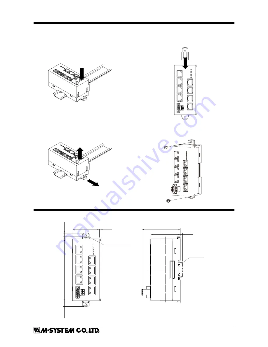
MOUNTING INSTRUCTIONS


DIN RAIL MOUNTING

• 

Mounting

1) Set the upper hook at the rear side of the module on the 

DIN rail.

2) Push in the lower.

1

2

• 

Dismounting

1) Push down the DIN rail mounter slider with tip of a 

minus screwdriver.

2) Pull the lower of the module.
3) Remove the upper hook of the module from the DIN rail.

1

2

3


SURFACE MOUNTING

1) Insert the DIN rail mounter slider until it clicks once, as 

shown below.

1

2) Mount the module with M4 screws referring the Exter-

nal Dimensions.  (Torque: 1.4 N·m)

EXTERNAL DIMENSIONS

  module: mm (inch)

50(1.97)

[3(.12)]

11

5(4.52)

[4 (.1

8)]

[4 (.1

8)]

[7 (.28)]

[7 (.28)

]

[4(.16)]

73(2.87)

55(2.17)

DIN RAIL
(35 mm wide)

2–4.3 (.17) dia Mtg Hole
4 (.16) deep

Содержание JC-CU

Страница 1: ...rations connected devices and connected wires may affect the protection level of this module when it is inte grated in a panel system The user may have to review the CE requirements in regard to the whole system and employ additional protective measures to ensure CE con formity POWER INPUT RATING OPERATIONAL RANGE Locate the power input rating marked on the product and confirm its operational rang...

Страница 2: ...6 LNK0 LNK5 LNK6 Status Indicator LED RJ 45 Modular Jack for Trunk Status Indicator LED RJ 45 Modular Jack for Feeder Power Supply Connector RJ 45 Modular Jack for Feeder Status Indicator LED Status Indicator LED PWR ERR ERR LED PWR LED SIDE VIEW SW1 ON SW1 1 2 3 4 Operating Mode Setting DIP SW SW1 Terminating Resistor Transfer Rate ON FRONT VIEW STATUS INDICATOR LED ID COLOR FUNCTION PWR Green ON...

Страница 3: ...TR 4 TR 5 NC 6 NC 7 NC 8 SLD Unused Unused Network Network Unused Unused Unused Shield Feeder CU1 CU2 CU3 CU4 CU5 CU6 1 NC 2 NC 3 TR 4 TR 5 NC 6 NC 7 NC 8 SLD Unused Unused Network Network Unused Unused Unused Shield Trunk CU0A CU0B COMMUNICATION CONNECTOR PIN ASSIGNMENT CODE 1 1 2 3 4 5 6 7 8 1 NC 2 NC 3 NC 4 TR 5 TR 6 NC 7 NC 8 SLD Unused Unused Unused Network Network Unused Unused Shield Feeder...

Страница 4: ...nting 1 Push down the DIN rail mounter slider with tip of a minus screwdriver 2 Pull the lower of the module 3 Remove the upper hook of the module from the DIN rail 1 2 3 SURFACE MOUNTING 1 Insert the DIN rail mounter slider until it clicks once as shown below 1 2 Mount the module with M4 screws referring the Exter nal Dimensions Torque 1 4 N m EXTERNAL DIMENSIONS module mm inch 50 1 97 3 12 115 4...

Страница 5: ...7 JC CU 7 11 1 2 3 1 2 3 FE PWR PWR POWER IN FE PWR PWR POWER OUT SLD NC NC NC TR TR NC NC CU0A COMMUNI CATION 1 2 4 3 6 5 8 7 SLD NC NC NC TR TR NC NC CU0B COMMUNI CATION 1 2 4 3 6 5 8 7 SLD NC NC NC TR TR NC NC SLD NC NC NC TR TR NC NC CU1 CU6 1 2 4 3 5 6 8 7 1 2 4 3 5 6 8 7 JC CU 3 12 SLD NC NC NC NC TR TR NC SLD NC NC NC NC TR TR NC CU0A COMMUNI CATION 1 2 4 3 6 5 8 7 CU0B COMMUNI CATION 1 2 4...

Страница 6: ...les at both end of the communication line The terminating resistor is incorporated in the feeder side port of the HUB module MOUNTING REQUIREMENTS module mm inch 125 4 92 CONFIGURATIONS The configurations such as communication mode and transfer rate must be same for all modules connected to the communication line The terminating resistor must be enabled for the mod ules at both end of the communic...

Отзывы: