

48NDVA
5-2-55, Minamitsumori, Nishinari-ku, Osaka 557-0063 JAPAN
Phone: +81(6)6659-8201 Fax: +81(6)6659-8510 E-mail: [email protected]
EM-9441-A Rev.9 P. 9 / 9
■
SIMULATED OUTPUT
1) Hold down [DOWN] for longer than 5 seconds to enter
the simulation mode until the Z and S indicators start
blinking, and the digital indicator shows ‘000.0,’ blinking.
2) Press [UP] or [DOWN] buttons to simulate a desired DC
output. Digital indicator is programmable from ‘000.0’ to
‘100.0’ %*
2
.
3) Hold down [SET] for longer than 5 seconds to get out of
the simulation mode.
*1. The [M] button remain activated for 1 minute after it
has been used to choose a indicator LED (programming
mode). During this period, pressing the [M] button briefly
is enough to choose another indicator. After 1 minute, it
turns to deactivated state.
*2. The bargraph goes off.
CALIBRATION PROCEDURE
This unit is calibrated at the factory to meet the ordered
specifications, therefore you usually do not need any cali-
bration.
For matching the indication to a receiving instrument or in
case of regular calibration, adjust the output as explained
in the following.
■
HOW TO CALIBRATE THE OUTPUT INDICATION
Use a signal source and measuring instruments of sufficient
accuracy level. Turn the power supply on and warm up for
more than 10 minutes.
1) ZERO: Apply 0% input and adjust the bargraph, digital
indicator and DC output to 0% following the each proce-
dure explained in “ADJUSTMENT PROCEDURE.”
2) SPAN: Apply 100% input and adjust the bargraph, digi-
tal indicator and DC output to 100% following the same
procedure.
3) Check ZERO adjustment again with 0% input.
4) When ZERO value is changed, repeat the above proce-
dure 1) – 3).
MAINTENANCE
Regular checking procedure is explained below:
■
CHECKING
Warm up the unit for at least 10 minutes. Apply 0%, 25%,
50%, 75% and 100% input signal. Check that the bargraph,
digital indicator and DC output for the respective input sig-
nal remains within accuracy described in the data sheet.
When the bargraph, digital indicator and DC output are out
of tolerance, recalibrate the unit according to the “CALI-
BRATION PROCEDURE” explained earlier.
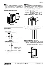
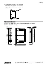
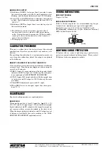
WIRING INSTRUCTIONS
■
SCREW TERMINAL
Torque: 0.6 N·m
■
SOLDERLESS TERMINAL
Refer to the drawing below for recommended ring tongue
terminal size. Spade tongue type is also applicable.
Applicable wire size: 0.25 to 1.65 mm
2
(AWG 22 to 16)
Recommended manufacturer: Japan Solderless Terminal
MFG.Co.Ltd, Nichifu Co.,ltd
6 (.24) max
3.3 (.13) max
mm (inch)
LIGHTNING SURGE PROTECTION
M-System offers a series of lightning surge protectors for
protection against induced lightning surges. Please contact
M-System to choose appropriate models.


