

48NDVA
5-2-55, Minamitsumori, Nishinari-ku, Osaka 557-0063 JAPAN
Phone: +81(6)6659-8201 Fax: +81(6)6659-8510 E-mail: [email protected]
EM-9441-A Rev.9 P. 7 / 9
LED OFF
LED Blinking
Mode Button
*
1
UP / DOWN Button
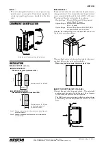
■
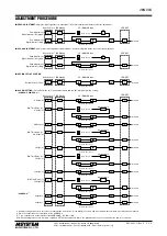
MOVING AVERAGE SAMPLE NUMBERS
P
M
Press at once
Moving Average
Sample Numbers
Increase / Decrease
Complete
Digital Indicator
SET
P
LED OFF
LED Blinking
Mode Button
*
1
UP / DOWN Button
■
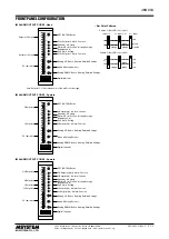
LED BRIGHTNESS ADJUSTMENT
P
M
Press at once
LED Brightness Adjustment
Increase / Decrease
*
2
Complete
Digital Indicator
SET
P
Digital Indicator
Press at once
*
1. Keep pressing at least for 3 seconds to activate Mode Button M. Press briefly for second and more times within 1 minute after it has been activated.
*
2. Pressing UP or DOWN button shifts the LED brightness in 7 levels. Factory default is set to 7, the brightest level.
*
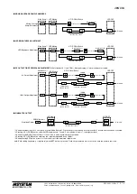
3. Keep pressing DOWN button at least for 5 seconds to enter the simulated output mode.
*
4. Pressing UP or DOWN button simulates the output between 000.0 and 100.0%.
*
5. Keep pressing SET button at least for 5 seconds to exit the simulated output mode.
Note: Each setting sequence is complete only when SET button is pressed. Once set, parameters are not lost even after the power is removed.
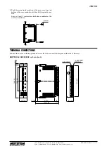
■
DC OUTPUT FINE ZERO/SPAN ADJUSTMENTS:
Set after input 0 % and 100 %. After performing, all alarm settings are cleared.
■
SIMULATED OUTPUT
Simulated Output
Increase / Decrease
*
4
Complete
SET
LED Blinking
DOWN Button
*
3
Z
S
LED OFF
Z
S
*
5
LED Blinking
0% Output Adjustment
UP / DOWN Button
Z
M
Press at once
Z
Press at once
Increase / Decrease
Complete
SET
Z
Z
LED ON
LED Blinking
(double speed)
100% Output Adjustment
S
M
Press at once
S
Press at once
Increase / Decrease
Complete
SET
S
S
LED ON
LED Blinking
(double speed)
Mode Button
*
1
LED OFF
Digital Indicator
Digital Indicator


