


15
To ensure the feasibility of the cable routes, it is suggested that the cables be
run prior to installation of the radio. Ensure slack is left in each cable so the
radio may be removed for servicing with all connections remaining intact.
D3100 is intended for installation within a weatherproof building, enclosure,
or vehicle. Typical installations are:
1.
Elevated (usually beyond unassisted reach) in an outside enclosure with
co-located antenna,
2.
Mounted inside a building and connected by RF cable to outside antenna
(usually above unassisted reach), or
3.
Vehicle installation with vehicle rooftop antenna.
Install the D3100 so that the LED indicators on the front panel are visible
during operation.
If installation is within the United States, it is recommended the unit be
installed by one of the many M/A-COM Authorized Service Centers located
throughout the U.S. Personnel at these centers are experienced in installations
of this type and can provide a safe, neat, and functional installation.
6.3
INSTALL D3100 RF MODEM
Mount the antenna, following the included instructions, in a manner that
prohibits or precludes the presence of anyone within the prescribed MPE
Radius when the transmitter is on (see Table 1-1). Connect the antenna to the
D3100 antenna connector.
In order for the D3100 to communicate with the RS-232 device, the D3100
data cable must be connected to the RS-232 device using an appropriate data
cable or cable adapter. The
accessory
Data/Programming/C-U Adapter Cable
(CA103067V1) that comes with the D3100 provides this interconnect
function. When assembling hand-made adapters, make sure the corresponding
function is connected between the D3100 Data Cable and other devices.
Connection of non-corresponding (dissimilar) functions may cause damage to
the D3100 or connected equipment and/or failure of proper performance. (See
Section 4.1 for the data connector functions.)
Connect the polarized power plug of the D3100 power cable to a
corresponding polarized socket on a 13.6 +/-15% DC, regulated power
supply, the Red lead to positive (
+
) and Black lead to negative or ground (
-
).
When power is on, the Yellow LED is on.
If the correct personality has been entered, correct data connection, antenna
connection, and power connection are made, and power is on, then D3100 is
ready for data calls.
Содержание P5100 Series
Страница 2: ...Installation and Operator s Manual MM21134 December 04 EDACS D3100 RF Modem...
Страница 14: ...Figure 5 1 Adapter Cable CA103067V1 13...
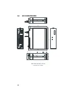
Страница 17: ...6 4 D3100 DIMENSIONS 14 144 176 158 50 51 D3100 MECHANICAL VIEWS DIMENSIONS IN MILLIMETERS 31 5 M4 4 Holes 16...
Страница 19: ...NOTES 18...
Страница 20: ...NOTES 19...
Страница 21: ...NOTES 20...
Страница 22: ...21...