
46
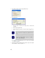
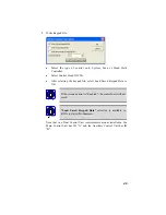
“Load Saved Keypad Data”
selection is available in
R19A (or later) ProGrammer.
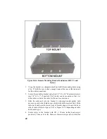
Note that in a Dual Control Unit front/remote mount installation, the Main
Control Unit has ID “B” and the Auxiliary Control Unit has ID “A”.
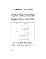
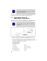
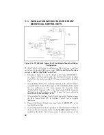
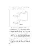
11.2 PROGRAMMING PROCEDURE -
REMOTE MOUNT CONFIGURATION
The Radio and Control Units must be programmed in a sequential procedure,
in order to provide each Control Unit with the proper identification code.
This programming procedure applies to uninstalled and
installed units.
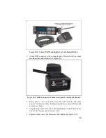
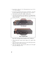
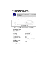
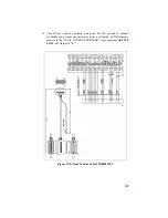
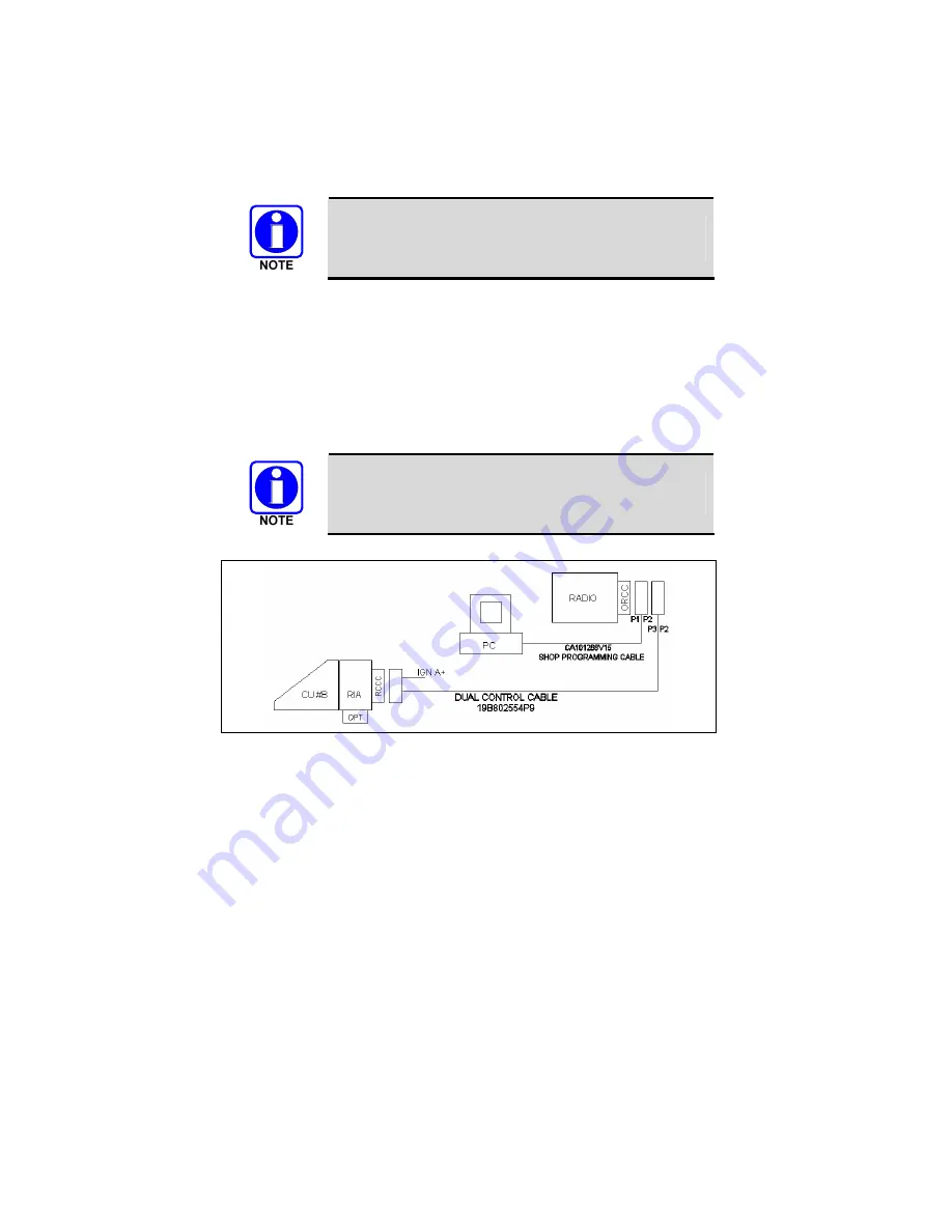
Figure 11-4: M7100 PC Programming Configuration Remote Mount
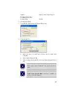
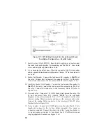
1.
Connect the M7100 Remote Mount Radio with ProGrammer, as shown in
Figure 11-4. Program the radio, using the shop programming cable
CA101288V15, with the following parameters:
NETWORK OPTIONS
Dual Control Setup
Dual Control
Enable
Audio Mode
Active or Parallel
Switching Mode
Independent or Slaved
Siren Light Controller
Unit A
Siren Light Connection
Unit A
Содержание P5100 Series
Страница 1: ...Installation Product Safety Manual MM102342V1 Rev Fp1 Sep 07 M7100IP Series Mobile Radio...
Страница 17: ...17 Figure 7 2 Rear Angle View of Radio 110W VHF Shown Figure 7 3 Interface Cables...
Страница 18: ...18 Figure 7 4 Option Cables...
Страница 27: ...27 Figure 10 4 Front Mount Extended Option Accessory Cable CA101288V2...
Страница 31: ...31 Figure 10 6 Remote Extended Option Control Cable CA101288V4...
Страница 64: ...64 Figure 12 3 Dual Radio Configuration Front Remote Mount PC Programming Procedure...
Страница 66: ...66 Figure 12 4 Dual Radio Configuration Remote Remote Mount PC Programming Procedure...
Страница 67: ...67 Figure 12 5 Dual Radio Control Cable CA101288V10...
Страница 71: ...71 NOTES...


