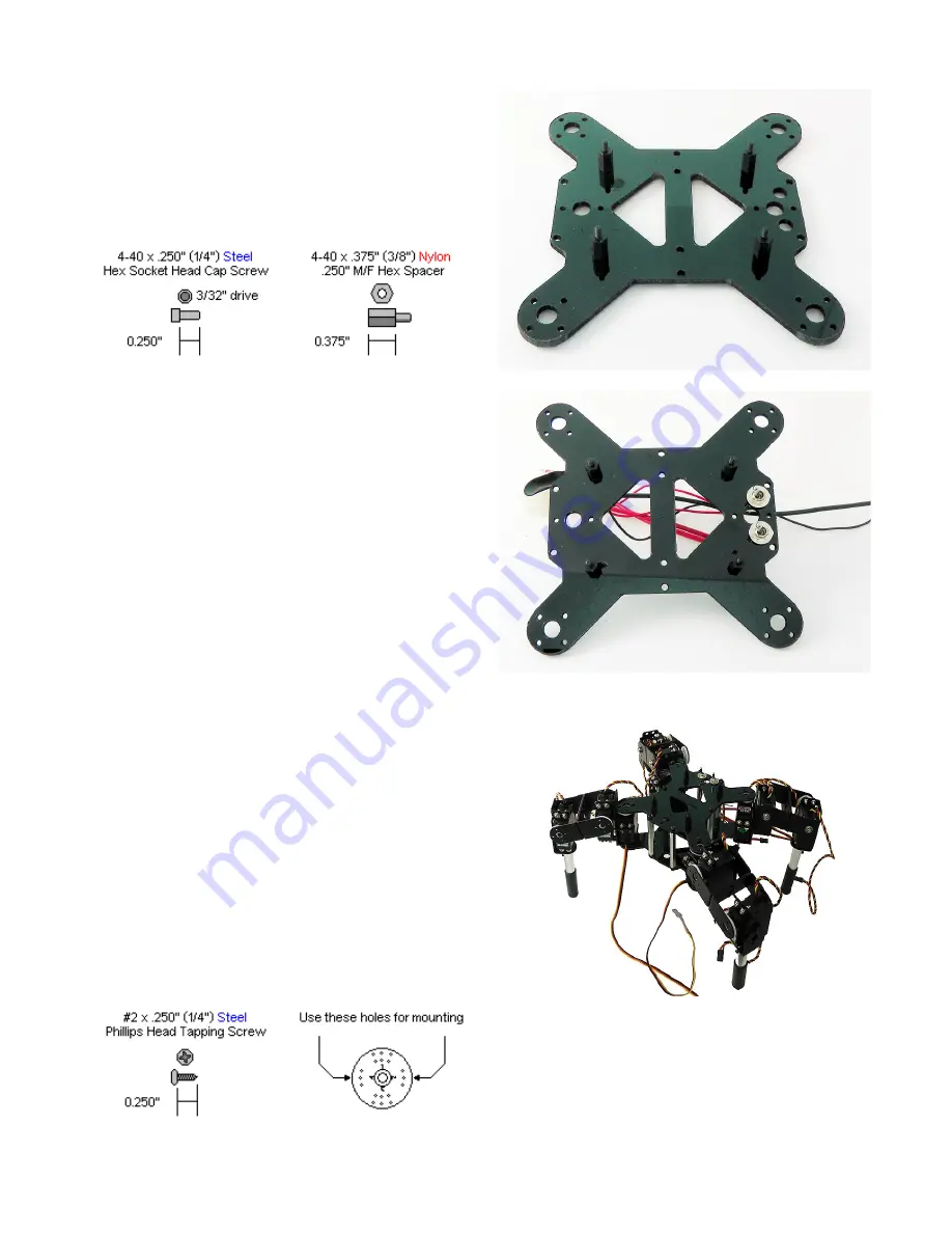
Step 3.
Use the second (top) plate for this step. Use four
4-40 x 1/4" hex socket screws to attach the 1/4"
long M/F plastic spacers to the plate. If you only
plan to use the SSC-32 and Bluetooth, use a F/F
spacer instead of the M/F spacer.
4 x
4 x
Figure 3.
Step 4.
Connect the 9V wiring harness and the servo
battery harness to the top plate. It does not
matter which switch connects to which hole.
Figure 4.
Step 5.
Attach the legs as shown, making sure to use
right or left legs as indicated. Use eight #2 x .
250" tapping screws (two per servo). The legs
should be positioned at 45 degrees to the body
and the servo should be receiving a 1500us pulse
(so the servo is positioned at 90 degrees). If you
are unsude how to do this, please refer back to
the leg assembly guide. In order to use the
sample code, the legs should be mirror images of
each other. The "rear" of the robot has the two
additional circular cutouts for the power
connectors.
8 x
Figure 5.


