5
INSTALLATION
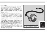
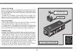
The Radio Interface can be fitted permanently to an aircraft by screw
fixing or plastic ties. Alternatively, the unit can be temporarily mounted
during flight using tube clips or Velcro.
During installation it is important to ensure that the unit and leads
do not interfere in any way with the aircraft control systems. Fixing
holes to mount the unit, or holes for cable routing, must not be drilled
in any structural member of the airframe.
Depending on the type of aircraft a specialist or licensed engineer
may be required by law to fit the equipment or inspect the installation.
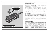
Screw Fitting
The interface has two threaded inserts built into the back of the unit
for mounting purposes. The threads accept M4 x 1.0 metric machine
screws and allow the body of the interface to be screwed directly to a
panel or bulkhead.
When mounting the unit using screw fasteners it is also important
to fit the locking washers: to prevent the screws working loose due to
vibration.
Velcro Attachment
As an alternative to screw fixing, the unit may be attached to a panel
or bulkhead using the Velcro pads supplied.
The two separate pads are adhesive-backed, and are easily fitted
to both the unit and a suitable flat surface. Before applying the pads
to the unit or aircraft, make sure that both the surfaces are clean and
dry and free from grease. Providing that good adhesive bonding is
achieved the Velcro pads offer a secure and flexible method of fixing.
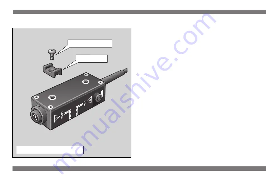
FIG 4 TIE SADDLE FITTING
SCREW FASTENER
TIE SADDLE
Содержание Micro System
Страница 1: ...INSTRUCTIONS RADIO RADIO INTERF INTERFA ACE CE...
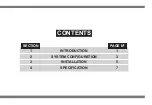
Страница 3: ...CONTENTS SECTION PAGE N 1 INTRODUCTION 1 2 SYSTEM CONFIGURATION 3 3 INSTALLATION 5 4 SPECIFICATION 7...
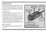
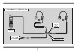
Страница 6: ...3 FIG 3 INTERFACE CONFIGURATION RADIO OPTIONAL P T T SWITCH BUILT IN P T T SWITCH INTERFACE UNIT...
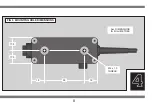
Страница 11: ...4 8 FIG 6 MOUNTING HOLE DIMENSIONS 17 5 17 5 18 18 55 M4 x 1 0 THREAD ALL DIMENSIONS IN MILLIMETRES...


