


7
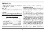
TECHNICAL INFORMATION
Unit size ................................
40 x 35 x 95 millimetres
Fitting area required ..........
110 x 35 x 110 millimetres
Radio Lead length .........................................
2 Metres
Stand-by power consumption ..................
< 100
µ
Amp
Transmit power consumption ...................
< 30 mAmp
P.T.T. Input .............................
Normally-Open Contact
SPECIFICATION
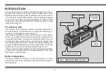
Technical information is provided in this section which may be useful
during the installation of the interface unit. Additional information can
be obtained directly from Lynx Avionics.
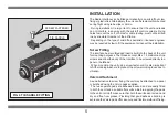
Radio Type
Each interface is configured to work with a specific make and model
of radio transceiver; the individual radio type configuration is marked
on the back of each unit.
P.T.T. Input
Several types of 'Push-To-Transmit' switch are available from Lynx
for direct connection to the interface unit and for use in different
applications. Connectors are also available which allow any 'Normally-
Open Contact' switch to be used to key a radio transmission.
Headset Extension Lead
Headset Extension Leads are available from Lynx for use with Micro
System Headsets. The leads are available in two-metre lengths, and
are fitted with one male connector and one female connector.
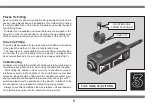
Radio Interference
The main cause of radio interference can usually be attributed to the
aircraft engine electrical system. High-tension ignition systems, and
strobe lights, emit strong electromagnetic signals which are received
by the radio antenna and amplified along with the radio reception.
Micro System communication equipment is virtually immune to
interference from electromagnetic radiation, but can not prevent
interference being introduced into the system by the radio. When
using a radio in an aircraft there are several simple steps that can be
followed to minimise the problem of interference, and considerably
improve the quality of radio reception.
Mount the radio antenna as far away from the engine as possible
and avoid routing the antenna lead close to the engine. Fit the engine
ignition leads with suppressors or suppressed plug caps as a matter
of course. If necessary screen the ignition leads using a braided
sleeve earthed to the airframe. Finally avoid fitting strobe lights and
their associated power leads near to the antenna and its lead.
©
Copyright Lynx Avionics MCMXCVII All Rights Reserved
Содержание Micro System
Страница 1: ...INSTRUCTIONS RADIO RADIO INTERF INTERFA ACE CE...
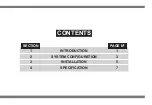
Страница 3: ...CONTENTS SECTION PAGE N 1 INTRODUCTION 1 2 SYSTEM CONFIGURATION 3 3 INSTALLATION 5 4 SPECIFICATION 7...
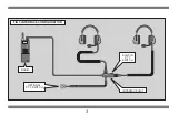
Страница 6: ...3 FIG 3 INTERFACE CONFIGURATION RADIO OPTIONAL P T T SWITCH BUILT IN P T T SWITCH INTERFACE UNIT...
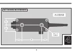
Страница 11: ...4 8 FIG 6 MOUNTING HOLE DIMENSIONS 17 5 17 5 18 18 55 M4 x 1 0 THREAD ALL DIMENSIONS IN MILLIMETRES...


