Luxman 7.1 Channel Reciever LR-8500 Скачать руководство пользователя страница 32

- 32 -

mated testing as a baseline and then make manual
adjustments to the crossover settings on a source-inde-
pendent basis. When this test is complete, a crossover
frequency will be shown to the right of the SPEAKER X-
OVER line on the menu screen.

Step 9

: When all measurements are successfully com-

pleted, the test signals will stop and a TEST DONE -
UNPLUG MIC message will appear in the second line of
the on-screen menu listings.

Unplug the microphone and store it in a safe place so that
it is available to recalibrate your system if needed due to
a change in speakers, preferred listening position, or a
major change in the room's furnishings (such as the addi-
tion of thick carpeting or plush furniture) that might
require different settings. To enter the settings to the
receiver's memory and return to the Master Menu, press
the 

5

/

b

Buttons so that the on-screen cursor is pointing

to RETURN TO MAIN MENU.

NOTE: If you wish to check the test results before exiting
the ROOM AUTO SETUP menu, press the 

5

/

b

Buttons

that the on-screen cursor is at the second line of the
menu listings, and then press the 

g

/

t

Buttons to scroll

through the list of speaker positions. The data on each
line will also be entered into the listings on the individual
SPEAKER SETUP, DELAY ADJUST and CHANNEL
ADJUST menus once you exit ROOM AUTO SETUP.
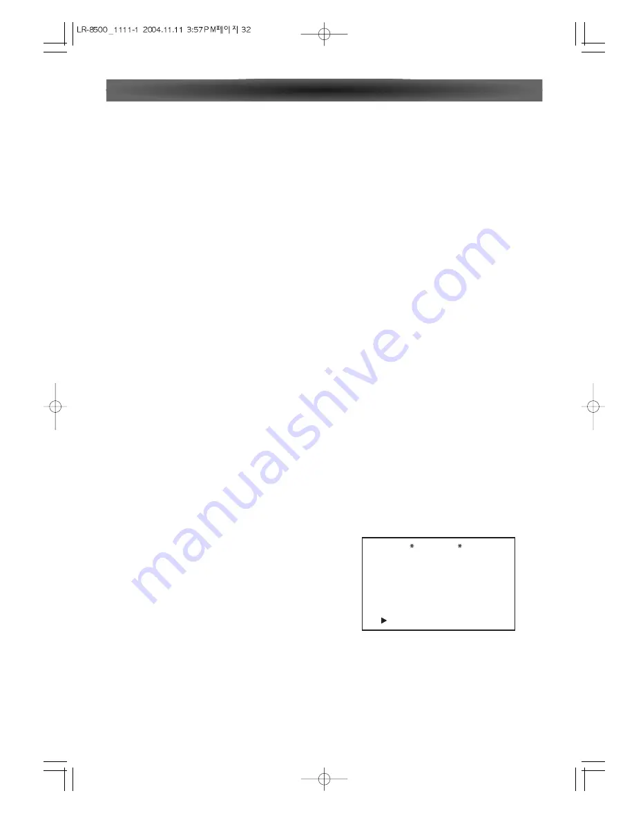
Step 10

: If the measurements are not successful due to a

missing or malfunctioning speaker, an ERROR message
and menu will appear. 
The ROOM AUTO SETUP system is programmed to look
for speaker pairs at the front left/front right, surround
left/surround right and surround back left/surround back
right positions. If the tests to any of those three channel
pairs indicates that one, but not both of the speakers in
the pair is present, the menu will show NONE next to the
speaker position where the tests did not report back that
a speaker is present. Should this message appear, make
note of the suspect speaker location, exit all menus and
turn the receiver off.

Check all speaker wire connections and then rerun
ROOM AUTO SETUP.

When you have successfully completed the ROOM AUTO
SETUP process and made any needed adjustments to the
input and surround mode configurations, your receiver is
ready for use. If you do not wish to make any manual
adjustments to the settings, you may skip the rest of this
section and proceed to the Basic Operation section of
this manual to learn how to operate LR-8500. For those
situations where you may wish to make a change to the
settings entered by ROOM AUTO SETUP.

Please check speaker
or connections.

: YES
: YES
: YES
: NONE

SBR
SBL
SL
SUB

FL
CEN
FR
SR

: YES
: YES
: YES
: YES

ERROR

BACK TO MAIN MENU

During this test, you will see a message in the last line of
the menu screen change as the volume level is adjusted.

• Speaker Check: The system will circulate a test signal to

determine which channels have a speaker connected.
During this test, you will see the name of each channel
position displayed while a signal is sent to that speaker.

NOTE: While this test detects whether a speaker is con-
nected to a particular output, it cannot determine
whether the speaker is in the correct position. (For exam-
ple, it can tell whether a speaker is connected to the
Surround Right output, but it cannot tell whether the
speaker is on the right or left side of your listening room.)
For that reason, we strongly recommend that you try to
listen as the tone circulates, matching the name shown
for each channel to the location of the speaker. If a tone
is heard from a  speaker position that does not match the
on-screen message, stop ROOM AUTO SETUP, exit the
menus, turn your receiver off and check for proper
speaker connections on the rear panel before resuming
the setup.

When this test is complete, YES will be shown to the right
of SPEAKER CHECK on the menu screen.

• Speaker Delay:

This test will circulate the tones again as

the name of each channel is shown to measure the dis-
tance from the microphone to each speaker. The results
of these tests will be used to set the delay time settings
for each active speaker position. When this test is com-
plete, a speaker-tomicrophone (listening position) dis-
tance will be shown to the right of SPEAKER DELAY line
on the menu screen.

• Speaker Level: 

This test circulates a test signal and mea-

sures the output from each active speaker position. The
results of the measurements are used to adjust the indi-
vidual channel outputs as needed, so that they are identi-
cal. This is an essential element of ensuring that surround
sound fields are properly reproduced. If desired, you may
use the results of the automated testing as a baseline and

then make manual adjustments to trim the output levels to
your personal taste. When this test is complete, an output
level adjustment number will be shown to the right of
SPEAKER LEVEL line on the menu screen.

• Speaker Size:

The measurements and calculations for

this test take place at the same time as the test signals
are circulated to calculate the output levels, and they are
used to determine whether the speakers in your system
are "large" or "small"  for the purposes of bass manage-
ment. (If desired, you may use the results of the automat-
ed testing as a baseline and then make manual adjust-
ments to the speaker size settings on a source-indepen-
dent basis.When this test is complete, an output level
adjustment number will be shown to the right of the
SPEAKER SIZE line on the menu screen.

• Speaker Crossover:

The measurements and calculations

for this test take place at the same time as the test signal
is circulated to calculate the levels, and they are used to
determine the crossover setting for each speaker in your
system to create a seamless transition between the fre-
quencies sent to your main speakers and subwoofer (if
available). If desired, you may use the results of the auto-

System Configuration

Содержание 7.1 Channel Reciever LR-8500

Страница 1: ...LR 8500 7 1 CHANNEL AV RECEIVER OWNER S MANUAL...

Страница 2: ...make any connection to the larger terminal which is marked with the letter E or by the safety earth symbol or coloured GREEN or GREEN and YELLOW The wires in the mains lead on this product are colour...

Страница 3: ...onfiguration 21 Tuner Operation 23 RDS 24 PTY 24 Video Operations 25 System Configuration 25 Function Setup 26 Surround Setup 26 Dolby Surround 27 Speaker Setup 28 Distance Adjust 29 CH Level Adjust 2...

Страница 4: ...ng Press the ENTER button for more than 5 seconds Note If the ENTER button is pressed for more than 5 seconds Standby mode all the memory will be erased Read this before operation As the unit may beco...

Страница 5: ...g DTS ES Extended Surround is a new multi channel digital signal format developed by Digital Theater Systems Inc While offering high compatibility with the conventional DTS Digital Surround format DTS...

Страница 6: ...he room at or slightly behind the listening position The center of the speaker should face into the room 90 110 22 30 135 150 0 Front Right Front Left Front Center Surround Left Subwoofer Surround Bac...

Страница 7: ...e insulation 2 Twist the bared wire ends tight to prevent short circuits 3 Loosen the knob by turning it counterclockwise 4 Insert the bare part of the wire into the hole in side of each terminal 5 Ti...

Страница 8: ...to the optional external audio power amplifier and video distribution system that delivers the source selected for ZONE II distribu tion PRE OUT SUB WOOFER jack Use this jack to connect a powered sub...

Страница 9: ...s and 3 optical jacks on the rear panel You can use these jacks to input PCM Dolby Digital and DTS bitstream signals from a CD DVD or other digital source components There is one digital output coaxia...

Страница 10: ...tors are for the R right channel and white con nectors are the for L left channel Be sure to connect the inputs and outputs of the video sig nals properly If you connect the S VIDEO or component signa...

Страница 11: ...level by using the 7 1 channel input level menu CONNECTING AN EXTERNAL POWER AMPLIFIER The PREOUT jacks are for connecting external power amplifiers Be sure to connect each speaker to the correspondin...

Страница 12: ...AM loop antenna The supplied AM loop antenna is for indoor use only Set it in the direction and position it to where you receive the clearest sound Put it as far away as possible from the unit tele v...

Страница 13: ...elect the top level group of surround modes Each press of the button will select the current or last used mode in each of the surround mode 8 7 6 5 4 3 2 1 Surround Mode selector n 6 Press these butto...

Страница 14: ...vels TV VID This button does not have a direct function on the LR 8500 but when used with a compatibly programmed VCR DVD or satellite receiver that has a TV VIDEO function pressing this button will s...

Страница 15: ...DVD only ZOOM Enlarges the DVD Audio image DVD only GUI Brings up the ON SCREEN display DVD only 16 15 14 13 12 11 10 9 8 7 6 REPEAT A B To repeat a specific section on a disc DVD only 1 ALL To repeat...

Страница 16: ...n to place the unit in Standby When it is used in a remote room with a sensor that is con nected to the ZONE II IR Input jack this button turns the ZONE II system on and off AMP Press this button to t...

Страница 17: ...y in use pressing one of these buttons will change the input MUTE When used in the room where the LR 8500 is located press this button to temporarily silence the unit When it is used in a remote room...

Страница 18: ...ency sound range select TREBLE ADJUST Press the 5 b buttons of remote control unit or the SELECT n 6 button to change the setting The level can be adjusted in 1 dB steps from 10 to 10 4 3 2 1 G F Basi...

Страница 19: ...ont right speakers only plus the subwoofer if installed and configured NOTE Once a program has been encoded with matrix surround information it retains the surround informa tion as long as the program...

Страница 20: ...in 1dB steps from 80 to 10 3 2 1 NOTE When the ZONE II system is turned on the input selected using the ZONE II menu will be fed to the ZONE II Audio Outputs on the rear panel The volume will be as se...

Страница 21: ...the surround sound decoder This allows the unit to sense the available speakers and automatically select decoding modes It is possible to receive multi channel surround sound without a center speaker...

Страница 22: ...to exit the Delay Adjust mode NOTE LR 8500 allows you to adjust the delay for the combined output of all speakers as a group This feature is called A V SYNC Delay it allows you to compensate for delay...

Страница 23: ...creases or decreases by one increment Stations may also be tuned directly To enter a station s frequency directly first select the AM or FM Next press the DIRECT button on the remote controller and en...

Страница 24: ...he RDS button PTY search will stop and search mode will be released automatically 3 2 1 NEWS brief announcements events public opinion reports actual situations AFFAIRS a kind of suggestion including...

Страница 25: ...play ENTER AMP OSD MAIN MENU FUNCTION SURROUND SPEAKER DISTANCE CH LEVEL PREFERENCE ZONE II ROOM AUTO SETUP SETUP SETUP ADJUST ADJUST SETUP SETUP SETUP Before using the unit you will probably want to...

Страница 26: ...igger the selection of one of the two DTS ES modes Newer discs with special DTS ES discrete encoding will be decoded to provide six discrete full bandwidth channels plus a separate low frequency chann...

Страница 27: ...a standard live performance theater Hall 1 Hall 2 The two Hall modes create sound fields that resemble a small Hall 1 and medium sized Hall 2 concert hall 5 Channel Stereo 7 Channel Stereo This mode...

Страница 28: ...hat digital sources are processed at their native sample rate For example a 48kHz digital source will be processed at 48kHz However the LR 8500 allows you to upsample the incoming 48kHz signals to 96k...

Страница 29: ...ngs The available choices at which point low frequency infor mation will be sent to the subwoofer rather than to the main speaker channel are 40Hz 60Hz 80Hz 100Hz 120Hz and 200Hz DISTANCE ADJUST Due t...

Страница 30: ...any of the configuration set tings manually or trim the settings provided by ROOM AUTO SETUP by following the instructions If you wish to configure your manually or if for some rea son your ROOM AUTO...

Страница 31: ...that you do not use ROOM AUTO SETUP and enter the configuration settings manually Step 7 The WARNING screen will automatically be replaced by the main ROOM AUTO SETUP menu While this screen is visible...

Страница 32: ...ignal to determine which channels have a speaker connected During this test you will see the name of each channel position displayed while a signal is sent to that speaker NOTE While this test detects...

Страница 33: ...CE button VCR SAT TV and the ENTER button at the same time for 2 seconds until the SEND LEARN indicator blinks twice Press the 5 or b button Each press will send out a series of codes from the remote...

Страница 34: ...06 007 011 042 IMPERIAL 011 INGELEN 042 056 052 038 INGERSOL 027 ITT 005 041 042 056 050 052 033 038 Brand CODE No JENSEN 042 JVC 042 056 030 052 KENWOOD 005 042 KRIESLER 045 031 KUBA 043 LLOYD 011 LO...

Страница 35: ...SAT Brand List VCR Brand List Brand CODE No SAISHO 002 010 025 027 SALORA 005 017 SAMSUNG 013 019 032 SANSUI 042 SANYO 000 003 005 025 038 SBR 018 029 SCHAUB LORENZ 041 042 056 050 052 038 SCHNEIDER 0...

Страница 36: ...142 149 078 ARTHUR MARTIN 053 139 117 120 122 123 125 128 ASA 050 055 057 113 134 ATLANTIC 099 111 AUDIOSONIC 054 AUSIND 053 AUTOVOX 099 144 055 019 057 069 BAIRD 083 BASICLINE 006 BAUR 011 BEKO 023...

Страница 37: ...143 053 077 090 ITT 001 140 058 105 109 122 123 128 148 129 130 134 135 083 089 JVC 033 KTV 099 Brand CODE No KAISUI 006 KARCHER 006 KENDO 098 KENNEDY 144 019 109 KORTING 050 059 111 KRIESLER 099 049...

Страница 38: ...42 148 149 088 SCHAUB LORENZ 001 058 109 122 123 128 129 130 134 SCHNEIDER 096 099 049 050 052 019 141 109 142 125 149 078 132 SEG 046 SEI 059 Brand CODE No SELECO 016 096 144 019 141 110 069 134 SHAR...

Страница 39: ...Local interference Digital audio feed paused Make certain AC power cord is plugged into a live outlet Check to see whether outlet is switch con trolled Make certain that all input and speaker con nect...

Страница 40: ...nse 15 Hz 16 kHz 1 1 5 dB Stereo Separation 1 kHz 40 dB Signal to Noise Ratio Mono 70 dB Stereo 68 dB AM Tuner Section Tuning Range 522 kHz 1 620 kHz 9 kHz steps Usable Sensitivity 55 dB m Total Harmo...

Страница 41: ...LUXMAN CORPORATION JAPAN...

Отзывы: