


5.
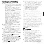
Set Backlight Option.
Your
wallstation is factory-set for the
backlight to be on. Set the
backlight for on or off using
switch 10.
4.
Address Wallstations.
Address all wallstations
on the control link. Refer to Lutron job drawings
for any preassigned job-specific address for each
control. For proper system operation, each wall-
station on a link
must
have a unique address. For
the maximum number of wallstations per control
link, please refer to the system installation guide.
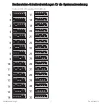
Please refer to page 2 of this installation guide for
the correct positions of the switches for each sys-
tem address. For systems with up to 32 wallsta-
tions on the control link, set switches 1-5 to one
of the positions (1-32) illustrated in the figure.
For example, to assign the wallstation to address
27, set the switches as follows:
Installation
Warning!
Always turn OFF the circuit
breaker/MCB or remove the main fuse from
the power line before doing any work.
Failure to do so can result in serious per-
sonal injury.
Prewiring: The control links require special wiring con-
siderations. Refer to the system installation guide and
Lutron job drawings for wiring restrictions and limita-
tions that apply to your specific project.
1.
Turn Power OFF.
Turn power OFF at circuit
breaker/MCB (or remove fuse).
2.
Mount Wallbox.
Mount standard U.S. 1-gang
wallbox, 2.75 in. (70 mm) deep (available from
Lutron; P/N 241-519). Check availability outside
the U.S.
3.
Prepare Wallstations.
Remove the faceplate,
adapter (for insert version), and button assembly
from the wallstation to access the address
switches.
ON
OFF
ON
OFF
ON
OFF
Set
Backlight
On
10
Set
Backlight
Off
10
27
1
2
3
4
5
6
ON
Address
Number
Switch
Positions
Note:
Switches 7, 8, and 9 are factory-set to
define the control type.
Installation Instructions
Occupant Copy
4