


2-2
X6
Des.
Control connections
21
UR
Ref. voltage 10 V
for ref. pot.
22
FSIN
Freq. ref. input
23
Ground
Control unit ref. point
24
STR
Start clockwise input
25
STL
Start counter-clockwise
input
26
UV
Control voltage 24 V DC
29
SOUTF
Digital freq. output
33
S1IND
Prog. digital input
34
S2IND
Prog. digital input
35
S3IND
Prog. digital input
36
SOUTA
Prog. analog output
41
S1OUT
Break contact of relay 1
42
Cent. spring of relay 1
43
Make contact of relay 1
44
S2OUT
Break contact of relay 2
45
Cent. spring of relay 2
46
Make contact of relay 2
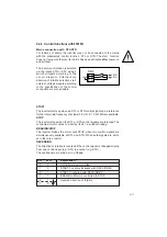
K1
Example of mains protection
connection
Y
Example of connection for ext.
mains filter
ground line
X
EMC ground clamps for easy
installation
of cable screen
VF1404M
VF1406M
VF1408M
VF1410M
wait 2 minutes
after mains off
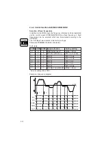
X1
Power connections
L1,L2,L3
Mains connection 3 x 400/460 V
U,V,W
Motor connection 3 x 400/460 V
X2/ + , -
Connection for DC-link coupling
X2/ RB
Connection for ext. braking resistor
X3
Socket for
control unit K
EY
P
AD
KP100
X4/51, 52
Motor PTC connection
1)
X5/
Connection terminal for
47,48,49,50
interface RS485
1)
or RS232
1)
1) Terminal assignment depends on design ordered
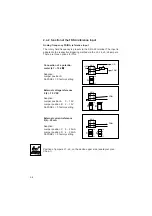
Attention:
Starting torque
of terminal X1
and X2
max. 0,4-0,5 Nm
-
RB
RB
+
41
42
43
44
45
46
n.c.
23
29
36
21
22
23
24
25
26
33
34
35
26
47
48
49
50
51
52
-
+
SOUTA
S2OUT
S1OUT
SOUTF
FSIN
UR
+24V
+10V
STR
STL
S1IND
S2IND
S3IND
V
DD
GND
A
B
RS485
1)
RB1
1)
W
V
U
L
3
L
2
L
1
M
3
K1
SI
L1
L2
L3
PE
3 x 400/460VAC
SI
SI
KP100
PTC
1)
UV
X6/1
X6/2
X5
X4
X3
X2
X1
X
0
0
1
Y
X
Содержание SMARTDRIVE VF1000 M Series
Страница 10: ...A 8 A 4 Manufacturer s declaration for frequency inverter ...
Страница 11: ...A 9 ...
Страница 13: ...A 11 ...


