LushOne Inca Synth Module Introduction, Joystick, Signal Processing
Joystick
Страница 1: ...LushOne Inca Synth Module Introduction Joystick Signal Processing Joystick ...
Страница 2: ... of new patches when used as a second or third module in a LushOne system Signal mixer and voltage processor Mix or modify signals by summing scaling and offsetting Noise source Random voltage source and percussive sound Sample and Hold Capture and hold voltage levels from clock Low Frequency Oscillator LFO Analogue thumbstick with switch 3 5mm mono Break in Breakout ...
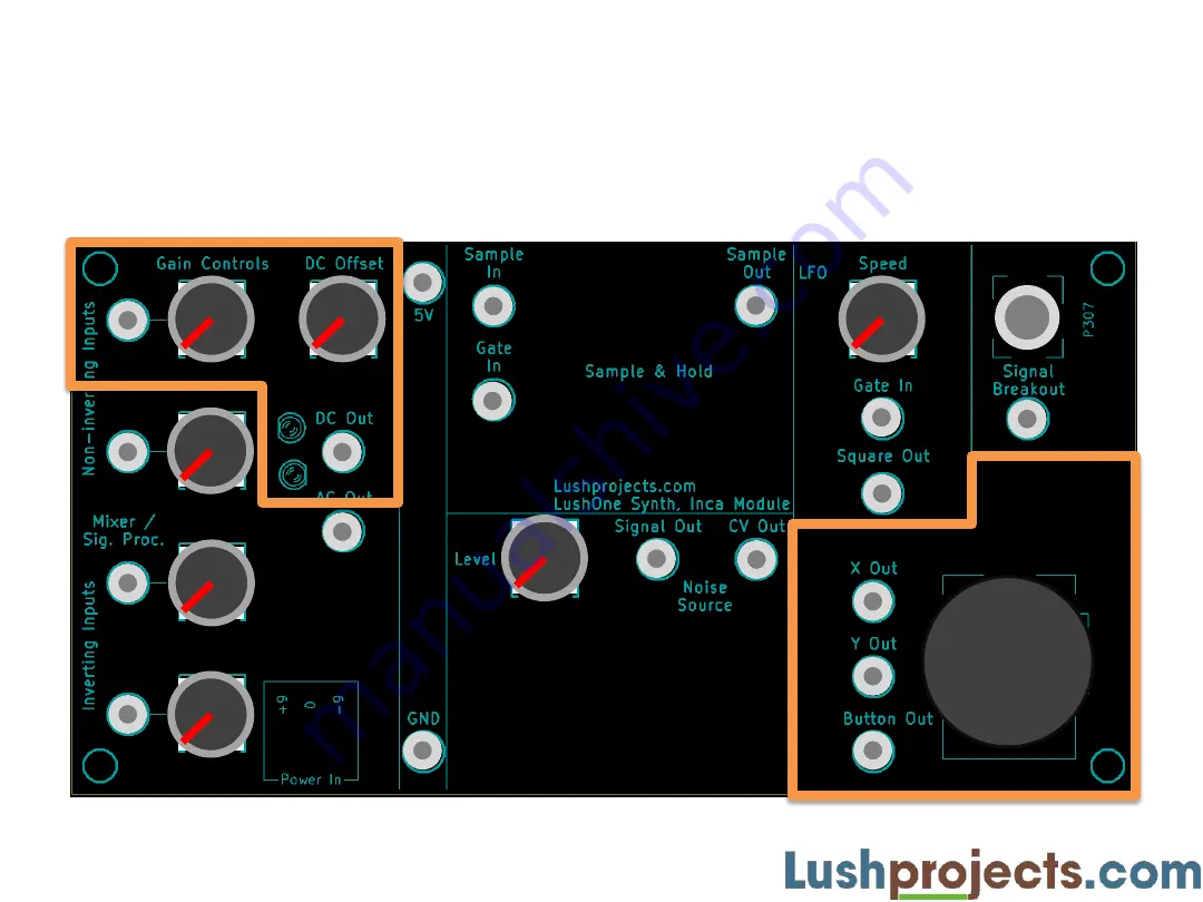
Страница 3: ...LushOne 301 LushOne Inca LushOne Inca layout and controls Joystick 2mm banana plug patch connector Mixer Signal Processor LFO Sample and Hold Break In Breakout 3 5mm mono jack socket Joystick Noise Source ...
Страница 4: ...4 LushOne 301 LushOne Inca In this teaching module Joystick Using the joystick Using one input of the mixer as a signal processor to manipulate a control voltage CV ...
Страница 5: ... two control voltages X Out and Y Out go from 0V to 5V based on the joystick position Button Out goes from 0V joystick not pressed to 5V joystick pressed Connect through the Mixer Signal Processor to change range of polarity of outputs The joystick makes me smile Joystick ...
Страница 6: ...e In 5V Inca Module LushOne Base Module Oscillator 2 OSC2 Set to Norm and CV H mode CV2 In OSC2 Out Joystick X Out Y Out OSC2 CV In OSC1 CV In LFO Square Out Gate In can be connected to one of 1 5V for continuous operation 2 Button Out for control by Joystick 3 LFO Square Out for regular beats Button Out ...
Страница 7: ...shown Twiddle joystick to get wide range of weird sounds Try different wave shapes Try connecting the Gate In to other sources Button Out on the joystick press joystick for sound Square Out on Inca LFO for repeating bursts Joystick Adjust for some bite Twiddle joystick No keyboard needed ...
Страница 8: ...ontrol over the full range of both oscillators What if you wanted to reduce the range of OSC1 so you got finer control Using the Mixer Signal Processor as a signal processor you can manipulate control voltages to Control the gain Add or subtract a voltage offset Invert the polarity of a signal Or any combination ...
Страница 9: ...ge increases Any of the non inverting or inverting inputs can be used Typically you want a control voltage output to use the DC Direct Current output DC out preserves the absolute level of the signal and allows you to add offsets Allows control voltages between 0V and 5V AC output will go negative Use the two LEDs to monitor the output voltage see next slide Non Inverting CV Input CV Output LEDs f...
Страница 10: ...ess goes from dim near 0V to bright at 5V DC signals will cause steady lights Slow AC signals will cause flickering lights Fast AC signals will cause steady lights again due to persistence of vision hiding the fast flicker With practice you will learn to infer the signal behaviour from the pattern of the lights DC Out 1V DC Out 5V DC Out 1V DC Out 0V DC Out 5V ...
Страница 11: ...nimum gain 0 Set the DC offset to the centre 0V Adjust the gain while moving the joystick up and down to vary the input Note that unity gain is approximately 1 3rd round the travel of the gain control Maximum gain is about x 3 Observe how the offset and gain controls can be used together to set the absolute voltage and the range of adjustment of the CV For non inverting inputs Vout Gain x Vin Offs...
Страница 12: ...n 3 Adjust the DC Offset to put the voltage in the safe range use a meter or LEDs to assess 4 Make connection from DC Out to the CV in 5 Increase the gain in small steps until you are happy After each step adjust the DC Offset as necessary Keep a short eye on the LEDs in particular watch for the negative LED lighting up Some inputs eg CV in to the filter are not too sensitive about the voltage in ...
Страница 13: ... Out stays within range 0V to 5V as you move the joystick left and right Bottom LED should not light Adjust DC Offset or Gain if needed Add patch lead to OSC1 CV In Follow procedure on previous slide to progressively adjust the Signal Processor Controls to get a range of effects you like while keeping within the allowed voltages Joystick Adjust for some bite Twiddle joystick Make this connection a...
Страница 14: ...ng around with the joystick Use the signal processor to change responses to control voltages Don t forget if you also have a contour you can invent patches involving all three modules Next time Using the Mixer to combine signals Interconnecting external signals ...