Acuity LS
Page 12
Operating Manual #OMA20200327
Starting Data Logging
1. Establish communications between the computer and Acuity LS device
. Refer to “Establishing
” above.
2. Select
“Start Data Logging”.
3.
Synchronize clock. Refer to “Clock Synchronization” above.
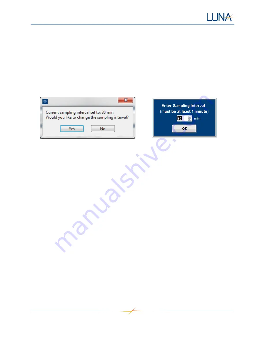
4. Set the sampling interval. Select "Yes
" to keep current sampling interval, or select “No” and enter
a new sampling interval (Figure 10
, left). Once new sampling interval is entered, select “OK”
(Figure 10, right).
Figure 10. Indication of current sampling interval, and prompt for changing sampling interval (left).
Sampling interval input window (right).
5. Use the Installation Description window to enter aircraft/asset, Acuity LS device, and LSP
information (Figure 11).
CAUTION:
DO NOT use any “,” or carriage return (enter key) characters in the provided text
boxes.
•
The Aircraft/Asset window can be used to enter specific information and notes about the
aircraft, asset, or structure being monitored.
•
The Acuity LS device window can be used to enter specific LSP or other information
about the materials and condition of the LSP, such as coating information if used.
•
Within the Acuity LS device window, answer the question, "Coating applied to gold IDE?".
The default answer is "No". If a coating is applied to the gold sensor then "Yes" can be
selected from the drop-down menu.
i. For "No" coating applied to the gold IDE, the high frequency gold conductance
(
Au 25kHz,
Column F in the data file) is a measure of surface contaminants.
1. The low frequency gold conductance (
Au 10Hz,
Column G in the data
file) should not be used for analysis when operating with "No" coating.
ii. "Yes" should only be selected if a coating is applied to the gold IDE.
For “Yes”,
both the low and high frequency measurements can be used to quantify coating
barrier properties.


