


30
occur if the machine tips over.
29. Never leave the machine running unattended. Turn
the power off and do not leave the machine until it co-
mes to a complete stop.
30. At all times hold the stock firmly.
Familiarize yourself with the following safety notices
used in this manual:
CAUTION:
This means that if precautions are not
heeded, it may result in minor injury and/or possible
machine damage.
WARNING:
This means that if precautions are not
heeded, it may result in serious injury or possibly even
death.
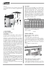
2. SPECIFICATIONS
Art.No. ..................................................... 21260 - 0209
Luna ............................................................ BSM 2260
Work table size .........................................750x250 mm
Table travel ................................ 80 mm (up and down)
Belt size ..................................................2260x150 mm
Belt table size ...........................................820x170 mm
Belt table tilt .......................................................0 - 90°
Dust chute diameter .........................................100 mm
Motor................................................................ 2200 W
Packing size ................. 1350x650x605 mm (one case)
The above specifications were current at the time this
manual was published, but because of our policy of
continuous improvement, the manufacturer reserves
the right to change specifications at any time and
without prior notice,without incurring obligations.
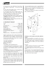
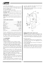
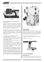
3. ASSEMBLY
Stand Assembly
Referring to Figure 1:
1. Remove all contents from the shipping container.
2. Clean all rust protected surfaces with a mild sol-
vent. Do not use paint or lacquer thinner, gasoline, or
mineral spirits; these will damage painted surfaces.
3. Attach the four rubber pads (A) to the bottoms of
the side panels (C) with four each hex nuts (B). The
hardware can be found in the bag with the rubber
pads.
4. Attach the side panels (C) to the front panel (D)
with four 5/16” x 5/8” hex cap screws, eight 5/16” flat
washers, four 5/16” lock washers, and four 5/16” hex
nuts (E). Hand tighten the hardware at this point.
NOTE:
Assemble the stand upside down to make sure
that the tops of the panels are flush.
5. Mount the shelf (F) to the inside of the stand with
two M5x10 pan head screws, two M5 flat washers and
two M5 lock washers (G).
6. Finish the stand assembly by attaching the rear pa-
nel (H) to side panels (C) with four 5/16” x 5/8” hex
cap screws, eight 5/16” flat washers, four 5/16” lock
washers, and four 5/16” hex nuts (J).
7. Make sure stand is sitting evenly on a level surface
before tightening hardware.
Fig. 1
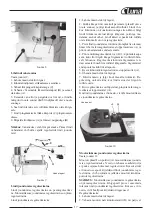
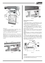
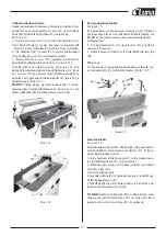
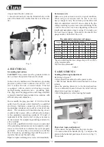
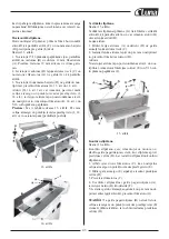
Installing table and motor unit to stand
WARNING:
The Table and Motor Unit is heavy! Use
great care and adequate resources when lifting the unit
up onto the stand! Failure to comply may cause serio-
us injury and/or damage to the sander and/or property!
Referring to Figure 2:
1. With the aid of another person, carefully lift the ta-
ble and motor unit (A) out of the shipping box, and
up onto the stand (B).
2. Line up threaded holes in the base (C) with the ho-
les in the stand (D).
3. Open the cabinet door (E) and through the opening
attach main unit to stand with two 5/16” x 1-1/4” hex
cap screws (F), two 5/16” lock washers (G) and two
5/16” flat washers (H). Tighten with a 12mm wrench.