background image

11

luminancebrands.com

Please contact 1-800-777-4440 for further assistance

U.L. Model No.: CF742PF

NOTE: CEILING COVER

OMITTED FOR CLARITY.

LISTED WIRE

CONNECTOR

SUPPLY WHITE 

(NEUTRAL) WIRE

FAN MOTOR 

WHITE WIRE

Figure 14

5.2

Securely connect the Fan Motor White Wire to the Supply 

White (neutral) Wire using Wire Connector (supplied) 

(Figure 14).

If you feel that you do not have enough electrical 

wiring knowledge or experience, have your fan 

installed by a licensed electrician.


5.1

Connect the Hanger Ball Green Ground Wire and the 

Hanger Bracket Green Ground Wire to the Supply Ground 

Conductor (this may be a bare wire or wire with green colored 

insulation). Securely connect Wires with Wire Connectors 

(supplied) (Figure 13).

5. How to Wire Your Ceiling Fan

This product is designed to use only those parts 

supplied with this product and/or any accessories 

designated specifically for use with this product 

by  Luminance Brands. Substitution of parts or 

accessories not designated for use with this product 

by  Luminance Brands could result in personal injury 

or property damage.


WARNING

!

NOTE: CEILING COVER

OMITTED FOR CLARITY.

GROUND 

CONDUCTOR 

SUPPLY WIRE

LISTED WIRE 

CONNECTOR

GREEN WIRE

(GROUND) FROM

HANGER BRACKET

GREEN WIRE

(GROUND) FROM

HANGER BALL

Figure 13

To avoid possible electrical shock, be sure electricity 

is turned off at the main fuse box or circuit breaker 

panel before wiring.

NOTE: If you are not sure if the outlet box is grounded, 

contact a licensed electrician for advice, as it must be 

grounded for safe operation.


WARNING

!

Turning off wall switch is not sufficient. To avoid 

possible electrical shock, be sure electricity is turned 

off at the main fuse box or circuit breaker panel before 

wiring. All wiring must be in accordance with National 

and Local codes and the ceiling fan must be properly 

grounded as a precaution against possible electrical 

shock.


WARNING

!

Содержание Kathy Ireland Home Summer Night CF742PFORB01

Страница 1: ...PF Net Weight 11 7 Lbs 42 Damp Location Ceiling Fan Owner s Manual CF742PFORB01 Oil Rubbed Bronze CF742PFWW01 Appliance White Model Numbers READ AND SAVE THESE INSTRUCTIONS INDOOR OUTDOOR 1 800 777 4440 Questions problems missing parts Before returning to the store Call Customer Service SUMMER NIGHT R ...

Страница 2: ...ical wiring have your fan installed by a licensed electrician NOTE This fan is suitable for use with solid state speed controls NOTE All set screws must be checked and re tightened where necessary before installation 1 Read your owner s manual carefully and keep it for future reference 2 Be careful with the fan and blades when cleaning painting or working near the fan Always turn off the power to ...

Страница 3: ...OTE Place the parts from the loose parts bags in a small container to keep them from being lost If any parts are missing call 1 800 777 4440 for replacement parts before proceeding 1 2 Remove the Fan Motor Assembly from the protective plastic bag Place the Fan Motor Assembly into the upper styrofoam with the top of the Motor facing up The upper styrofoam serves as a holder for the Fan during the f...

Страница 4: ...utlet boxes commonly used for support of light fixtures are not acceptable for fan support and may need to be replaced Consult a qualified electrician if in doubt WARNING Turning off wall switch is not sufficient To avoid possible electrical shock be sure electricity is turned off at the main fuse box or circuit breaker panel before wiring All wiring must be in accordance with National and Local c...

Страница 5: ...roperly grounded as a precaution against possible electrical shock WARNING 3 1 Disconnect Electrical Power to the Branch Circuit at the Circuit Breaker Panel or Main Fuse Box before attempting to install the Ceiling Fan to the Outlet Box Figure 1 3 Ceiling Fan Assembly 3 2 Pass the Three 80 Motor Wires through the opening in the Ceiling Cover Be sure the Ceiling Cover is oriented correctly Figure ...

Страница 6: ...n The Hairpin Clip must be properly installed to prevent the Clevis Pin from working loose Pull on the Hanger Ball to make sure the Clevis Pin is properly installed SET SCREW MOTOR COUPLER SET SCREW 3 5 While pulling up on the Hanger Ball retighten the Two Set Screws previously loosened in the Motor Coupler to secure the Hanger Ball 3 5 Downrod Assembly into place Figure 4 NOTE The set screws must...

Страница 7: ... Attachment Screws from the Motor before installation of Blade Assemblies Figure 7 Discard the Spacers and Spacer Screws SPACER ATTACHMENT SCREW SHIPPING SPACER Figure 7 3 Ceiling Fan Assembly Continued BLACK WIRE 6 TO 9 INCHES WHITE WIRE HANGER BALL 1 2 INCH BLUE WIRE 3 6 The Fan comes with Blue Black and White Wires that are 80 long Measure up approximately 6 to 9 inches above top of Hanger Ball...

Страница 8: ...the adjacent flange screws re engage and reseat the flanges then tighten the screws again A spare M5 x 13mm Flange Screw is in the hardware bag if needed 3 9 IMPORTANT THE SIDE OF THE FAN BLADE HAVING THE RIB LINE MUST BE FACING UPWARDS AS SHOWN IN FIGURE 8 Mount the Blade Flange to the Fan Blade using Three M5 x 10mm Washer Head Blade Screws supplied Figure 8 Repeat this procedure for other Four ...

Страница 9: ... could wobble or fall WARNING 4 1 Securely attach the Hanger Bracket to the Outlet Box using the Two Screws supplied with the Outlet Box Figure 11 TWO SCREWS SUPPLIED WITH OUTLET BOX HANGER BRACKET ANTI ROTATION TAB OUTLET BOX Figure 11 FLOOR AT LEAST 7 CEILING Figure 10 4 How to Hang Your Ceiling Fan To avoid possible electrical shock be sure electricity is turned off at the main fuse box or circ...

Страница 10: ...NG OUTLET BOX HANGER BRACKET HANGER BALL DOWNROD ASSEMBLY NOTE CEILING COVER SUPPL Y WIRES AND FAN WIRES OMITTED FOR CLARITY HANGER BRACKET HANGER BALL HANGER BALL GROOVE ANTI ROTATION TAB Figure 12 4 2 Carefully lift the Fan and seat the Hanger Ball Downrod Assembly on the Hanger Bracket that was just attached to the Outlet Box Figure 12 Be sure the Groove in the Ball is engaged with the Anti Rot...

Страница 11: ...y accessories designated specifically for use with this product by Luminance Brands Substitution of parts or accessories not designated for use with this product by Luminance Brands could result in personal injury or property damage WARNING NOTE CEILING COVER OMITTED FOR CLARITY GROUND CONDUCTOR SUPPLY WIRE LISTED WIRE CONNECTOR GREEN WIRE GROUND FROM HANGER BRACKET GREEN WIRE GROUND FROM HANGER B...

Страница 12: ... OMITTED FOR CLARITY BLACK BLUE WIRES WHITE WIRES GREEN WIRES Figure 16 5 4 After connections have been made turn Wires upward and carefully push Wires into the Outlet Box with the White and Green Wires on one side of the Outlet Box and position the Black and Blue Wires on the other side of the Outlet Box Figure 16 Check to see that all connections are tight including ground and that no bare wire ...

Страница 13: ...ur new Ceiling Fan Please call Customer Service at 1 800 777 4440 if you have any questions about installation and operation of this Ceiling Fan 13 luminancebrands com Please contact 1 800 777 4440 for further assistance U L Model No CF742PF 6 Final Assembly CEILING COVER LOCKWASHERS 2 THREADED STUDS 2 KNURLED KNOBS 2 Figure 18 To avoid possible fire or shock make sure that the electrical wires ar...

Страница 14: ...eiling Fan on again Figure 19 The Fan Blades will turn in the opposite direction and reverse the airflow Reverse Switch Information Season Rotation Direction Summer Counter Clockwise Winter Clockwise 7 2 Cut the 3 Speed Switch Pull Chain to a desired length optional Connect the Wood Pendant supplied to the 3 Speed Switch Pull Chain by sliding the Wooden Pendant small hole first onto the Pull Chain...

Страница 15: ... Fan Light Kits Ceiling Fan Light Controls Downrod Extension Kits 10 Energy Efficient Use of Ceiling Fans Ceiling fan performance and energy savings rely heavily on the proper installation and use of the ceiling fan Here are a few tips to ensure quality and product performance Choosing the Appropriate Mounting Location Ceiling fans should be installed or mounted in the middle of the room and at le...

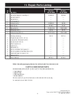
Страница 16: ...16 U L Model No CF742PF 11 Repair Parts 1 9 3 4 13 11 10 7 8 14 2 PARTS BAG 12 13 14 11 10 9 17 17 18 15 15 6 5 16 16 ...

Страница 17: ...el No Model No No Description CF742PFORB01 CF742PFWW01 Hanger Ball Assembly Consisting of 760750 36 760750 3 1 Hanger Bracket 1 2 Hanger Ball 1 3 3 5 Downrod 1 4 Ceiling Cover 1 760169 24 760169 5 Blade Sets 5 762022 1 762022 6 Flange Sets 5 763109 ORB 763109 WW 7 Wiring Harness 1 763110 763110 8 Switch Housing Cover 1 763112 ORB 763112 WW Parts Bag Containing 763111 763111 1 9 Threaded Studs 8 32...

Страница 18: ...to make sure wire connectors in switch rattling housing are not rattling against each other or against the interior wall of the switch housing 4 Screws holding flanges to blades are loose 4 Tighten screws securely 3 Fan wobbles 1 Set screws in motor coupler is loose 1 Tighten the set screws securely in the motor or shakes coupler excessively 2 Set screw in hanger ball downrod 2 Tighten the set scr...

Страница 19: ...minance Brands Ceiling Fan Product component or Luminance Brands Ceiling Fan Product accessory caused by normal wear and tear rather than due to defects in materials or workmanship Loss or damage resulting from conditions beyond our reasonable control including without limitation unforeseeable operating environmental conditions repairs not made at Our factory or authorized service center use of pa...

Страница 20: ...he fan housing The date code can be found on the carton and on top of the fan housing stamped in ink on a white label You should record this data above and keep it in a safe place for future use Questions problems missing parts Before returning to the store Call Customer Service 1 800 777 4440 www luminancebrands com Retain this manual for future use 370 Falls Commerce Pkwy Cuyahoga Falls OH 44224...

Отзывы: