


21
EN
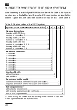
1 DeSIgn DeScrIPtIon
The SR11 system is composed of BR11 controllers situated in one ho-
using and connected to the mould with heated channels by means of a
dedicated ZP11 connection set.
The housing in the shape of a cassette, ensures appropriate
exploitation conditions and the required protection degree against
electric shocks. Multiple connectors ensure an easy connection
with the mould.
Connecting cables of a special design have been applied in the SR11
system (fig. 1 and 2 - page 39).
In SR11-11X1X, SR11-3XX1X, SR11-6XX1X and SR11-8XX1X
systems, thermocouple and heater wires are led in a common bundle and
shielded by a metallic shield connected to the earth potential.
Signalling wires of SR11-6XX2X and SR11- 8XX2X systems are led in
separate cables, also shielded.
Sensors are connected by compensating wires.
To connect the mould to the connection set, GP11 socket sets are op-
tionally offered.
On the rear side of the SR11 system there are the connection cable to the
injection mould and the DB-25 signalling connector to connect the RS-485
interface, the logic input and alarm relay contact outputs.
For SR11-6XXXX and SR11-8XXXX systems versions with separate
connector of heaters and thermocouples are accessible, and with
a common connector of heaters and thermocouples (SR11-6XX1X,
SR11-8XX1X).
In SR11-11XXX and SR11-3XXXX systems, only versions with common
thermocouple and heater wires are accessible.
The lay-out of connectors for system versions are shown on fig. 4, 5, 6
and 7 (pages 40-41).


