background image


79 

8.1.5. Browsing and Erasing of files from the CF Card 


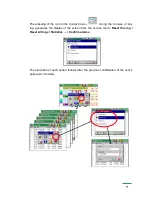
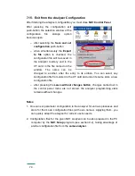
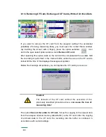
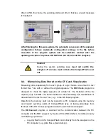
After  selecting  the  icon 

in the ND1 Panel Control, file names saved in 

the  CF  card  are  displayed  in  the  file  browser.  After  selecting  the  given  file  and 

confirming its selection, it may be deleted from the CF card.  


If  the  card  is  not  inserted  into  the  analyzer  or  it  is  not  formatted,  a  message 

informing about its lack is displayed. 


Delete of selected 

file 

File 

selection 

Exit from the menu  

return to the ND1  

 control panel 

Содержание ND1

Страница 1: ...ANALYSER OF 3 PHASE POWER NETWORK PARAMETERS ND1 TYPE User s Manual LZAE Lumel S A Sulechowska 1 65 022 Zielona G ra Poland EU...

Страница 2: ...1 UNPACKING 11 3 2 INSTALLATION IN THE PANEL 12 3 3 ANALYZER OPERATING CONDITIONS 12 4 ANALYZER CONSTRUCTION 13 4 1 LCD SCREEN WITH TOUCH PANEL 13 4 2 COMPACTFLASH MEMORY CARD USB INTERFACE LED DIODE...

Страница 3: ...LCD SCREEN 35 7 1 3 PARAMETER PROGRAMMING COMPACTFLASH FORMAT 35 7 1 4 PARAMETER PROGRAMMING OTHER 36 7 2 INPUTS 36 7 2 1 PARAMETER GENERAL 36 7 2 2 PARAMETER AVERAGE 37 7 2 3 PARAMETER PROGRAMMING T...

Страница 4: ...FILE BROWSER 68 7 13 EVENTS LOGS 68 7 13 1 BROWSING AND HANDLING OF EVENT LOGS 70 7 14 EDITION OF USER S MESSAGES 72 7 15 EXIT FROM THE ANALYZER CONFIGURATION 74 8 SELECTED ELEMENTS FROM THE CURRENT...

Страница 5: ...RAMS ON THE PC 85 9 1 KD CONNECT PROGRAM 85 9 1 1 INSTALLATION OF THE USB DRIVER 85 9 2 ND1 SETUP APPLICATION 86 9 3 KD CHECK APPLICATION 86 10 TECHNICAL DATA 87 11 ORDER CODES 92 MAINTENANCE AND GUAR...

Страница 6: ...ndows Exchangeable CompactFlash external memory with capacity up to 4 GB Communication interfaces Ethernet 10 Base T Modbus TCP IP Slave USB 1 1 Device RS 485 Modbus Master RS 485 Modbus Slave Analog...

Страница 7: ...nsation effectiveness 1 3 Firmware Update The manufacturer reserves the right to a continuous improvement and makes changes in design and specifications in the product without warning This especially...

Страница 8: ...ises occurring in industrial environments acc to EN 61000 6 2 and EN 61000 6 4 standards The improper connection of the supply communication interfaces and measuring signals and the use of equipment i...

Страница 9: ...res All shields should be earthed unilaterally near the analyzer A common earth conductor with other devices must be avoided Apply the general principle that wires group of wires leading different sig...

Страница 10: ...emble instruments only in the area protected against electrostatic discharges Use conductive materials to dissipate electrostatic charges in the working area Use only antielectrostatic packings to sto...

Страница 11: ...ng A Take the ND1 analyzer out from the shipping packing The data plate with the version code factory number and supply parameters are placed on the analyzer casing Before unpacking check the conformi...

Страница 12: ...panel the seal protects the part behind the panel against the influence of risks appearing from the frontal part of the panel resulting from the IP65 protection grade The analyzer is fixed to the pan...

Страница 13: ...r the visualization of measuring data and the configuration of analyzer parameters an LCD TFT 5 7 graphical screen integrated with a touch panel is applied Fig 4 2 LED diode Door with lock access to C...

Страница 14: ...emical agents touch the screen with fingers only do not use hard and sharp objects which can damage the flexible surface of the touch panel clean softly with a cotton cloth impregnated with a detergen...

Страница 15: ...through the USB interface You can also save or delete selected files on the card To connect the computer to the analyzer through the USB socket use the shielded USB AM BM cable of 1 8 m long delivere...

Страница 16: ...rating state Red color of the diode signals the storage of data on the CompactFlash memory card In this operating state you must not take out the card from the seat risk to lose measuring data 4 3 Ter...

Страница 17: ...85 230 253 V a c d c 24 V d c 30 mA Auxiliary supplies destined to supply external systems RS485 1 RS485 2 Ethernet Communication interfaces RS485 Modbus Master RS485 Modbus Slave Ethernet 10 Base T E...

Страница 18: ...system electromechanical relays AL1 6 Alarms are normally open contacts NO Parameters of the alarm system are given in the chapter Technical Data Connection of the control signal to terminals of the...

Страница 19: ...Ethernet socket diodes Yellow diode lights when the analyzer is connected to the Ethernet network and does not light otherwise Green diode Tx Rx lights irregularly when the analyzer uploads and colle...

Страница 20: ...on of Measuring Signals Note 1 To connect measuring signals use the plug in strip from ND1 accessories 2 Signal connections are presented on figures in the view from the ND1 terminal plate side Fig 4...

Страница 21: ...se network Indirect measurement with the use of 2 current transformers and 2 or 3 voltage transformers Fig 4 7 Four wire network Indirect measurement with the use of 3 current transformers and 2 or 3...

Страница 22: ...22 Fig 4 8 Three wire three phase network Indirect measurement Fig 4 9 Three wire three phase network Indirect measurement...

Страница 23: ...23 Fig 4 10 Four wire network Direct measurement Fig 4 11 Four wire network Semi indirect measurement...

Страница 24: ...24 Fig 4 12 Four wire network Indirect measurement with the use of 4 current transformers...

Страница 25: ...e introduced Push buttons for global navigation Push buttons for navigation on accessible options Exceeded level storage over 90 of the card capacity Change of data presentation form CF card partially...

Страница 26: ...between menu windows Introduction of a number or string Option selection from the list or the dialogue Context help 5 1 3 Information Messages Warning Symbol of error occurrence Question Information i...

Страница 27: ...Graphic signs used during the visualization process are presented below Note some symbols occur only on selected screens Range exceeding of the measured value over the upper limit and the alarm state...

Страница 28: ...y inputs suitably input in the high state and input in the low state 5 2 2 Colors of Measuring Values The following colors of measuring data are introduced for informative purposes Black color 123 5 M...

Страница 29: ...sses Next the screen of data visualization appears in form of the last analyzer state before the supply turned off After touching the screen any place the Context Menu appears 6 1 Context Menu Button...

Страница 30: ...audits or alarms Selection of service options available for the currently open screen Entry to the edition and configuration of analyzer parameters You can add to the Context Menu as above 5 additiona...

Страница 31: ...e icon of ND1 analyzer configuration menu The log in window appears At the first start there is only the Administrator user The logging follows without the password simply accepting the window The Adm...

Страница 32: ...the first start it is a default configuration at next starts the configuration changed by the user in the ND1 control panel Open configuration from file The selection of the configuration file from s...

Страница 33: ...g parameters section 7 7 setting of Ethernet interface parameters section 7 8 setting of Modbus interface parameters Master Slave section 7 9 setting of access principles for analyzer configuration ch...

Страница 34: ...ce of the CF card service of the LCD screen setting of user messages and selection of the context menu option 7 1 1 Parameter Programming Basic Item Function 1 Edition of the device symbol 2 Edition o...

Страница 35: ...off 5 min 12 hours 2 Setting of the screen brightness 3 Calibration of the touch screen see section 8 2 4 Setting acceptance 7 1 3 Parameter programming CompactFlash format Item Function 1 CompactFla...

Страница 36: ...ntext Menu see section 6 1 3 Setting acceptance 7 2 Inputs After pressing the icon the configuration window of the analyzer measuring input parameters becomes open setting of the network base frequenc...

Страница 37: ...ratio values 5 Setting acceptance Note For a correct measurement of the zero current you must prepare suitable terminal connections 7 2 2 Parameter Average Item Function 1 Setting of the averaging per...

Страница 38: ...case of tariff activation by binary inputs a physical binary input from 1 to 4 corresponds to relevant tariff number Please remember that only one tariff can be activated in the given time at the high...

Страница 39: ...General and Control tabs become open Note only alarms from 1 to 6 have representation on physical outputs Remaining alarms from 7 to 12 have a logic character 7 3 1 Parameter Programming General 1 Se...

Страница 40: ...value is below above the alarm value Lower limit Upper limit Range On Range Off the alarm is enabled when the signal value is between or beyond set alarming values Lower limit Upper limit 4 Edition of...

Страница 41: ...tion in percentage of the range n a Hyst value n a Edition of the value in the range unit positive value n a Edition of the value in the range unit positive value Time Hysteresis value in the time uni...

Страница 42: ...42 Fig 7 2 Functional diagram of the Value On alarm type Fig 7 3 Functional diagram of the MAX alarm type taking in consideration the hysteresis of Value and Time type...

Страница 43: ...pported in the analyzer as long as it will not be confirmed by the operator Accept Switching the alarm state off in the analyzer by the operator During the analyzer operation you can select in the con...

Страница 44: ...e of the selected alarm 8 Setting of message storage in the alarm log Enabled information about the occurrence of alarm states will be saved in the log Disabled messages about alarm states will not oc...

Страница 45: ...n the window for the selection and configuration of 1 4 analog outputs become open 7 4 1 Selection of the Analog Output 7 4 2 Parameter Programming General 4 Switching analog outputs 3 2 1 Selection o...

Страница 46: ...log output 7 Settings acceptance 7 4 3 Parameter Programming Range Item Function 5 Edition of the input range in Setting of the lower and upper range values Lower Upper limit 6 Edition of the output r...

Страница 47: ...10 min U RMS limits Configuration of RMS voltage quality parameters for 10 minutes period default settings acc to EN 50160 Min deviation 100 setting of admissible U RMS deviation percentage downwards...

Страница 48: ...rcentage upwards for a 100 probability Time deviation X setting of the time percentage in which the frequency has to be situated in definite limits Min deviation X setting of the admissible frequency...

Страница 49: ...lue and hysteresis in percentage of the nominal U MRS value 7 Setting acceptance Power quality parameter definitions Voltage interruption state in which the voltage is lower than 1 of the declared vol...

Страница 50: ...e exceeding the normally accepted tolerance interval in reference to the rated or declared voltage 7 6 Visualization After pressing the icon the window of selection and visualization parameter configu...

Страница 51: ...1 2 L 2 3 L 3 1 3 Color selection for all remaining quantities 4 Setting acceptance 7 6 2 Parameter Screens Measuring data can be presented on following screen types Large Digital view Harmonics Stati...

Страница 52: ...e digital view Harmonics There are 6 data groups for presentation Harm U Harm I Harm table U Harm table I Harm table U Harm table I Harm table Umax Harm table Imax Alarm state Selection of data group...

Страница 53: ...entation Statistics U Statistics I Analog indicators This view is a set of four displays modeled on analog meters Alarm symbol if occurs is appeared under the form of a bell above the unit area Select...

Страница 54: ...gram Three data groups are available for presentation Phrasal diagram U I and L L If values of phase parameters in relation to which the chart is calibrated are indeterminated or take zero the calibra...

Страница 55: ...ry Power Quality view Energy quality parameters are presented on two screens PQ Main and PQ Summary Modbus Master state This table view depicts Modbus Master inputs state only those which are enabled...

Страница 56: ...orm by the user The selection of the screen type and parameters from the programmed data set for it can be made from the Context Menu and from the information bar on the currently displayed screen Exa...

Страница 57: ...ub range I 4 Edition of the sub range P 5 Edition of remaining parameters Percentage deviation from rated values for remaining subranges list of exceptions shown in a full scale Demonstration of all s...

Страница 58: ...nly the number of data selected for the visualization max 50 and they do not influence storage settings 7 6 5 Parameter Programming Other auto views Auto views delay setting of screen switching time i...

Страница 59: ...e context Menu 7 7 Archivization After pressing the icon in the ND1 control Panel the selection and configuration window of archiving parameters for 1 4 measuring groups become open Maximum archiving...

Страница 60: ...group one can enable or disable the given group edit the group name select maximally up to 12 measuring quantities and set the storage period of measuring data In the Events tab you can select binary...

Страница 61: ...elect events that are common for all enabled groups Archiving of measuring data switching off The archiving is switched off when the selected binary input is in the logic state 1 Data storage in a CF...

Страница 62: ...be indicated during the checking of files by the KD Check program Since the CSV text file includes a digital signature every defined number of measurement series the file area line range from to whic...

Страница 63: ...compatibility issues User s access with NTLM auth It is the authorization protocol used in networks built on the base of the Microsoft Windows NT system or newer Recommended for users of these systems...

Страница 64: ...upper limits 7 Edition of the Modus device description 8 Copying settings into another input 9 Acceptation of input settings interface input Item Inputs configuration Registers 10 Address edition 11 S...

Страница 65: ...s Disabled Enabled Port 502 6 Setting acceptance 7 10 Security After pressing the icon the window of 1 8 analyzer user s edition and setting principles of their access to the analyzer configuration is...

Страница 66: ...ed Users have access after giving the password to the option of analyzer parameter configuration in ND1 Control Panel Item Function 1 Enabling Disabling of the selected user from 1 8 2 Edition of the...

Страница 67: ...installed in the analyzer storage state of the CF memory card and internal buffer become open There is also the service tab of the analyzer program updating and the service maintenance The service mai...

Страница 68: ...an appropriate message appears 7 13 Events Logs Following kinds of logs are available in ND1 Audit log Alarm log Energy log Power Quality log Dips and Swells log Information concerning elements of the...

Страница 69: ...arameters will be displayed in the Energy Log Information about voltage and frequency quality parameters defined in the EN 50160 standard are saved in the Power Quality Log Information about Wells and...

Страница 70: ...og Enabled Disabled 7 13 1 Browsing and Handling of Event Logs After pressing the screen during the visualization of measuring data the Context Menu is displayed The pressure of the icon generates the...

Страница 71: ...u during the browse of any log generates the display of the screen from the service menu Reset this log Reset All logs Statistics Confirm alarms The execution of each option follows after the previous...

Страница 72: ...g option is available Reset all statistics which reset all min and max of all measuring values 7 14 Edition of User s Messages You can program in the analyzer configuration menu for the given measurin...

Страница 73: ...73 As the need arises defined messages as above can be saved by the operator in the alarm log during the analyzer operation...

Страница 74: ...e entry to its edition You can select any configuration file from stored in the CF card and under its name store a new configuration file after pressing the Leave without changes button changes carrie...

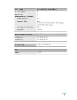
Страница 75: ...window the information about CF appears If a CF card is not present an appropriate message is given in the Storage tab When the card is inserted in the analyzer the following parameters are showed dat...

Страница 76: ...hem and a system of files is created During the formatting of the CF card the LED diode on the analyzer frontal plate changes the green color into red 8 1 3 Data storage on the CF Card During the anal...

Страница 77: ...color it is recommended to transfer data from the memory card to the PC computer as fast as possible format the card or replace it for another empty one Caution After exceeding the nominal capacity o...

Страница 78: ...t measuring data before its removal from the analyzer select the option Save archive data to CF card This operation copies all current data from the internal buffer into the CF card After selecting th...

Страница 79: ...are displayed in the file browser After selecting the given file and confirming its selection it may be deleted from the CF card If the card is not inserted into the analyzer or it is not formatted a...

Страница 80: ...till the recording is performed in the internal buffer while the save on the CF card is locked till the time of the displayed message acceptation Before the message acceptation you can replace the CF...

Страница 81: ...h screen must be carried out in case of incorrect reaction on pressing the icons buttons in windows displayed on the LCD screen After pressing this option and confirming the selection and reading the...

Страница 82: ...ated New firmware and software versions in the form of updated files will be available for interested users on the page http www lumel com pl After copying the new update file to the ND1 directory on...

Страница 83: ...stored in text format files csv with or without the digital signature The KD Check program is designed to check the digital signature of a data file The limitation of the file capacity is up to 8 MB T...

Страница 84: ...ng the ND1 Setup program are the same as to the analyzer menu described in the user s manual But please take notice of some differences to handle the ND1 Setup program the mouse and computer keyboard...

Страница 85: ...s operating system After connecting the Analyzer to the USB port of your PC the operating system will ask you for necessary drivers Found New Hardware Wizard appears Insert the CD disk delivered with...

Страница 86: ...or applications destined for the MS Windows environment The installation program is located on the annexed CD disk to the analyzer in the ND Setup folder To begin the program installation start the in...

Страница 87: ...Q 0 0 6000 0 var 999 00 Mvar Ku 1 Ki 1 0 5 Active Power Factor PF 1 000 0 1 000 0 5 PF Power Factor P S Coefficient tg 10 00 0 10 00 1 Ratio of active power to reactive power angle between I and U 180...

Страница 88: ...U RMS A C 0 0 200 0 accuracy 0 5 from nominal value event detection based upon 1 cycle RMS voltage programmable thresholds in percent of nominal voltage Additional conversion errors in of the basic er...

Страница 89: ...TFT 320 240 pixels with touch panel external data support CompactFlash up to 4 GB internal memory buffer 6 MB power input supply circuit voltage circuit current circuit 28 VA 0 2 VA 0 2 VA casing pro...

Страница 90: ...ply 85 253 V d c a c 40 400 Hz reaction against decays and supply recoveries preservation of data and the device state during the decay work continuation after the supply recovery input signal 0 0 005...

Страница 91: ...5 USB interfaces 50 V measuring system 500 V cat III for 57 7 V 100 V and 230 V 400 V options cat II for 400 V 690 V option electromagnetic relays supply 300 V altitude ASL 2000 m Electromagnetic comp...

Страница 92: ...0 with an extra quality inspection certificate 1 acc to customer s request X after agreeing with the Manufacturer Note The ND1 analyzer is equipped with 6 alarms electromechanical relays 4 analog out...

Страница 93: ...rument has been used in compliance with the instructions the Manufacturer guarantees to repair it free of charge After the Guarantee Period One should turn over the instrument to repair in a certified...

Страница 94: ...ER OUR SERVICES IN THE PRODUCTION OF ALUMINIUM ALLOY PRESSURE CASTINGS PRECISION ENGINEERING and THERMOPLASTICS PARTS SUBCONTRACTING of ELECTRONIC DEVICES SMT PRESSURE CASTINGS and OTHER TOOLS QUALITY...

Отзывы: